Better Pump Efficiency
ဥပမာ ၁
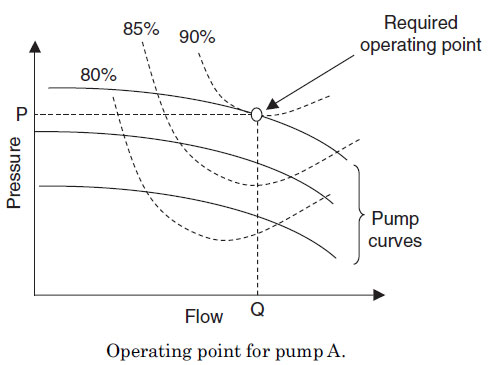
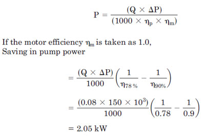
Chilled Water System တစ္ခုတြင္တပ္ဆင္ထာေသာ Chilled
Water Pump A ၏ Flow rate မွာ 80 L/s ၿဖစ္ၿပီး head မွာ 150 kN/m2 ၿဖစ္သည္။
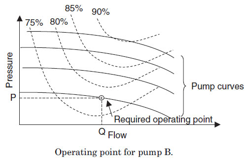
ထို pump A ၏ efficiency မွာ 78% ၿဖစ္သည္။ အကယ္၍ ထို pump ကို 90 percent
efficiency ရွိေသာ အၿခား pump B ၿဖင့္ ေၿပာင္းလဲတပ္ဆင္လုိက္လွ်င္ pump
power မည္မွ်သက္သာသြားမည္နည္း။
 |
 |
 |
ဥပမာ၂
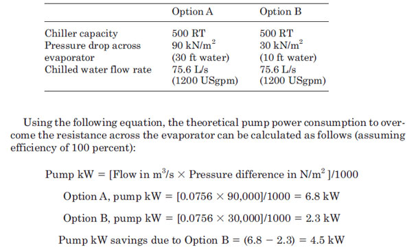
Capacity တူညီေသာ Chiller ႏွစ္လံုး A ႏွင့္ B တုိ့ ၏ Data မ်ားအားလံုးမွာ Pressure Drop Across မွ လြဲ၍တူညီၾကသည္။
Chiller A ၏ Pressure Drop Across မွာ 30 ft of water
ၿဖစ္ၿပီး Chiller B ၏ Pressure Drop Across မွာ 10 ft of water ၿဖစ္သည္။
ထုိ Chiller B ကို ေရႊးခ်ယ္ၿခင္းေၾကာင့္ သက္သာေသာ power ကို ရွာပါ။
ေမးခြန္းမ်ား
ေမးခြန္း (၁) A pump တစ္လံုးသည္ 1200 rpm
ႏွင့္ေမာင္းေနသည္အခုိက္ 200 L/s ကို တြန္းပို့နိုင္ၿပီး 45 kW လုိအပ္သည္။
ထုိ pump speed သည္ 1100 rpm အထိ ေလ်ာ့က်ခဲ့လွ်င္ new flow rate and power
consumption ကို တြက္ၿပပါ။
ေမးခြန္း (၂) A pump တစ္လံုးသည္ 1200 rpm
ႏွင့္ေမာင္းေနသည္အခုိက္ 200 L/s ကို တြန္းပို့နိုင္ၿပီး သည္။ သုိ့ေသာ္
တစ္ခ်ိဳ ့ေသာအခ်ိန္တြင္ (actual operating conditions) water flow မွာ 35
L/s ၿဖစ္ၿပီး the pump
motor သည္ 25 kW ကို သံုးစြဲသည္။ What will the reduction in pump power consumptionbe if the pump speed is reduced to provide the design water flow of 20 L/s?
motor သည္ 25 kW ကို သံုးစြဲသည္။ What will the reduction in pump power consumptionbe if the pump speed is reduced to provide the design water flow of 20 L/s?
ေမးခြန္း (၃) The condensers of two different chillers of equal capacity have pressure
drops of 80 kN/m2 and 40 kN/m2, respectively. If the water flow rate
required is 150 L/s, calculate the saving in pump power for the condenser
water pump if the chiller with the lower pressure drop is used instead of
the chiller with the higher pressure drop.
drops of 80 kN/m2 and 40 kN/m2, respectively. If the water flow rate
required is 150 L/s, calculate the saving in pump power for the condenser
water pump if the chiller with the lower pressure drop is used instead of
the chiller with the higher pressure drop.
ေမးခြန္း (၄)A pumping system တစ္ခုသည္40 L/s ႏွင့္ a
head of 120 kN/m2 လုိအပ္သည္။ ထုိ pump ၏ efficiency မွာ 65 % ၿဖစ္သည္။ 65
% efficiency ရွိေသာ pump ကို 85% ရွိေသာ pump
ၿဖင့္ေၿပာင္းလဲတပ္ဆင္လုိက္လွ်င္ power မည္မွ် သက္သာမည္နည္း။
ပန့္နွင့္သက္ဆုိင္ေသာ ပုစၦာမ်ား
ဥပမာ ၁
55 kW ေမာ္တာတပ္ဆင္ထားေသာ Pump တစ္လံုးသည္
တစ္မိနစ္လွ်င္ အပတ္ေရ ၁၄၀၀ (1400 rpm) ႏွင့္လည္ပတ္ေနၿပီး တစ္စကၠန့္လွ်င္
လီတာ flow rate =120 L/s တြန္းပိုနုိင္စြမ္းရွိသည္။ အကယ္၍ထုိ ပန့္သည္
တစ္မိနစ္လွ်င္ အပတ္ေရ ၁၁၂၀ (1120 rpm) သို့က်သြားလွ်င္ တစ္စကၠန့္လွ်င္
လီတာမည္မွ်သာ တြန္းပို့နုိင္မည္နည္။ (new flow rate ကိုရွာပါ)။ power
consumption မည္မွ်ၿဖစ္မည္နည္း ။
Q1 _ 120 L/s
P1 _ 55 kW
N1 _ 1400 rpm
N2 _ 1120 rpm
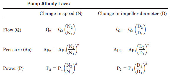
Q2 = Q1 x (N2/N1) = 120 x (1120/1400) = 96 L/s
P2 = P1 x (N2/N1)3 = 55 x (1120/1400)3 = 28 kW
 အထက္ပါ ဥပမာ၏ အဓိပါၸယ္မွာ ပန့္သည္ တစ္မိနစ္လွ်င္ အပတ္ေရ
၁၄၀၀ မွ တစ္မိနစ္လွ်င္ အပတ္ေရ ၁၁၂၀ (1400 rpm to 1120 rpm) သို
က်ဆင္းသြားလွ်င္ ထုိပန့္၏ စြမ္းအင္သံုးစြဲမွဳ (power consumption) သည္ ၅၀%
က်ဆင္းသြားလိမ့္မည္။ တနည္း ၅၅ကီလိုဝပ္ သံုးစြဲေနသည္မွ ၂၈ကီလိုဝပ္
သာသံုးစြဲလိမ့္မည္။ (55 kW to 28 kW). သတိၿပဳရန္ အခ်က္မွာ ပန့္ မွ
တြန္းပို့နုိင္ေသာ Pressure Head သည္ လည္း speed က်ဆင္းမွဳ၏ ႏွစ္ထပ္ကိန္း
အတိုင္းက်ဆင္းသြားလိမ့္မည္။ ထုိေၾကာင့္ Pump Affinity Laws သည္ Energy
Saving အတြက္ အလြန္အသံုးဝင္ေသာ Formula ၿဖစ္သည္။ ထို Affinity Lawsကို
“cube law” ဟုလည္းေခၚတတ္ၾကသည္။ အဓိပါၸယ္မွာ ပန့္ သို့ Fan ၏ သံုးစြဲေသာ
ပါဝါသည္ ထုိ ပန့္ သို့ Fan ၏ လည္ပတ္နွန္းသံုးထပ္ကိန္းႏွင့္ တုိက္ရုိက္
အခ်ိဳးက်သည္။ (power & speed3).
အထက္ပါ ဥပမာ၏ အဓိပါၸယ္မွာ ပန့္သည္ တစ္မိနစ္လွ်င္ အပတ္ေရ
၁၄၀၀ မွ တစ္မိနစ္လွ်င္ အပတ္ေရ ၁၁၂၀ (1400 rpm to 1120 rpm) သို
က်ဆင္းသြားလွ်င္ ထုိပန့္၏ စြမ္းအင္သံုးစြဲမွဳ (power consumption) သည္ ၅၀%
က်ဆင္းသြားလိမ့္မည္။ တနည္း ၅၅ကီလိုဝပ္ သံုးစြဲေနသည္မွ ၂၈ကီလိုဝပ္
သာသံုးစြဲလိမ့္မည္။ (55 kW to 28 kW). သတိၿပဳရန္ အခ်က္မွာ ပန့္ မွ
တြန္းပို့နုိင္ေသာ Pressure Head သည္ လည္း speed က်ဆင္းမွဳ၏ ႏွစ္ထပ္ကိန္း
အတိုင္းက်ဆင္းသြားလိမ့္မည္။ ထုိေၾကာင့္ Pump Affinity Laws သည္ Energy
Saving အတြက္ အလြန္အသံုးဝင္ေသာ Formula ၿဖစ္သည္။ ထို Affinity Lawsကို
“cube law” ဟုလည္းေခၚတတ္ၾကသည္။ အဓိပါၸယ္မွာ ပန့္ သို့ Fan ၏ သံုးစြဲေသာ
ပါဝါသည္ ထုိ ပန့္ သို့ Fan ၏ လည္ပတ္နွန္းသံုးထပ္ကိန္းႏွင့္ တုိက္ရုိက္
အခ်ိဳးက်သည္။ (power & speed3).
ဥပမာ၂
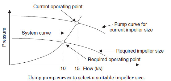
ပန့္တစ္လံုး၏ ေမာ္တာသည္ 1400 rpm
ႏွင့္ေမာင္းေနသည္အခ်ိန္တြင္ Flow rate 10 L/s ရရွိရန္ဒီဇုိင္းလုပ္ထားသည္။
သို့ေသာ္ pipe system တြင္ တပ္ဆင္၍ အသံုးၿပဳသည့္အခါ အမွန္ရရွိေသာ Flow rate
မွာ 15 L/s ၿဖစ္ၿပီး ပန့္ေမာ္တာသည္ 15 kW ကို သံုးစြဲသည္။ ထုိပန့္အား
ဒီဇုိင္း Flow rate ၿဖစ္ေသာ 10 L/s ကို ေရာက္ေအာင္ pump speed ကို VSD
အသံုးၿပဳ၍ က်ဆင္းေအာင္ၿပဳလုပ္ခဲ့လွ်င္ ပန့္ Power
သံုးစြဲမွဳမည္မွ်က်ဆင္းသြားမည္နည္။
Pump affinity laws အရ
From pump affinity laws, the pump speed can be reduced to give the design flow
as follows:
New pump speed _ 1400 ထ (10/15) = 933 rpm
New power consumption = 15 ထ (10/15)3 = 4.5 kW
Reduction in pump power consumption =15 – 4.5 = 10.5 kW
ဤနည္းသည္ Estimation ခန့္မွန္းမွဳမ်ားၿပဳလုပ္ရန္အတြက္သာ
အသံုးဝင္သည္။ တိက်ေသခ်ာေသာ ရလာဒ္မ်ားရရွိရန္အတြက္ ပန့္ထုပ္လုပ္သူမ်ား
(Pump Manufacturer) ထံမွရရွိသည္ pump curves ကို အသံုးၿပဳၾကသည္။ Pump
Manufacturer သို့ ပန့္ model ကြဲၿပားသလုိ ပန့္တစ္လံုးၿခင္းစီ၏
performance သည္လည္းကြဲၿပားသည္။
ပန့္တစ္လံုး၏လက္ရွိေမာင္းေနသည့္ flow rate ႏွင့္
pressure ကို တုိင္း၍ pump curves ေပၚတြင္ လက္ရွိ operating point ကို
မွတ္သားနုိင္သည္။ ထို တုိင္း၍ရသည့္ flow rate ႏွင့္ pressureသည္ပင္
အသံုးၿပဳ၍ system curve ကိုလည္းခန့္မွန္းနုိင္သည္။ system curve သည္
parabolic relationship ရွိေသာ curve ၿဖစ္သည္။ သို့ parabolic curve
ဟုခန့္မွန္းဆြဲနုိင္သည္။
ထုိကဲ့သုိ့ pump curves ေပၚတြင္ လက္ရွိ operating
point ႏွင့္ system curve ကိုဆြဲသားၿပီးေနာက္က်န္ ဆက္စပ္ေနသည့္ Parameter
မ်ားကို တြက္ယူရရွိနုိင္သည္။
 ပန့္ ပုစၦာမ်ား
၁. ပန့္တစ္လံုးသည္ 1200 rpm
ႏွင့္ေမာင္းေနသည္အခ်ိန္တြင္ Flow rate 200 L/s ကိုတြန္းပို့နုိင္ၿပီး ထုိ
ပန့္၏ေမာ္တာသည္ 45 kW ပါဝါကို consumesလုပ္သည္။
ထုိပန့္ ၏ speed သည္ 1100 rpm သို က်ဆင္းသြားလွ်င္ new flow rate and power consumption ကို ရွာပါ။
၂. ပန့္တစ္လံုး၏သည္ 1200 rpm ႏွင့္ေမာင္းေနသည္အခ်ိန္တြင္ Flow rate 20
L/s ရရွိရန္ဒီဇုိင္းလုပ္ထားသည္။သို့ေသာ္ pipe system တြင္ တပ္ဆင္၍
အသံုးၿပဳသည့္အခါ အမွန္ရရွိေသာ Flow rate မွာ
35 L/s ၿဖစ္ၿပီး ထုိပန့္သည္ ၏ ေမာ္တာသည္ 25 kW ပါဝါကို
consumes လုပ္သည္။ အကယ္၍ water flow ကို ဒီဇုိင္းလုပ္ထားသည့္ 20 L/s သို့
ေရာက္ေအာင္ Speed ကို ေလွ်ာ့ခ်လိုက္လွ်င္ မည္မွ် pump power consumption
ေလ်ာ့က်သြား သည္ကို ရွာပါ
၃. Cooing capacity တူညီေသာ Chiller ႏွစ္လံုး၏ condensers မ်ားသည္ မတူညီေသာ pressure
drops ရွိၾကသည္။ Chiller A ၏ pressure drops မွာ 80 kN/m2 ၿဖစ္ၿပီး
Chiller B ၏ pressure drops မွာ 40 kN/m2 ၿဖစ္သည္။ Chiller ႏွစ္လံုး၏
condensers water flow rate မ်ားသည္ 150 L/s ၿဖစ္ၾကသည္။ အကယ္၍ pressure
drops မ်ားသည့္ Chiller A ကို သံုးမည့္အစား pressure drops နည္း သည့္
Chiller B ကိုသံုးလွ်င့္ ထို Chiller ႏွင့္ တြဲ၍တပ္ဆင္ထားေသာ condenser
water pumpမ်ား၏ pump power saving ကို တြက္ပါ။
၄. A pumping system တစ္ခုအတြက္လုိအပ္ေသာ ပန့္၏ Flow 40
L/s လုိအပ္ၿပီး pressure head သည္ 120 kN/m2လိုအပ္သည္။ ထို application
အတြက္ 65 percent efficiency ရွိသည့္ ပန့္ကို ေရႊးမည့္အစား ပိုေကာင္းသည့္
85 percent efficiency ပန့္ကိုေရြးခ်ယ္လုိက္လွ်င္ power မည္မွ်သက္သာ
နုိင္မည့္နည္။ (ေခြ်တာနုိင္မည္နည္း)
Q1 _ 120 L/s
P1 _ 55 kW
N1 _ 1400 rpm
N2 _ 1120 rpm
Q2 = Q1 x (N2/N1) = 120 x (1120/1400) = 96 L/s
P2 = P1 x (N2/N1)3 = 55 x (1120/1400)3 = 28 kW
From pump affinity laws, the pump speed can be reduced to give the design flow
as follows:
New pump speed _ 1400 ထ (10/15) = 933 rpm
New power consumption = 15 ထ (10/15)3 = 4.5 kW
Reduction in pump power consumption =15 – 4.5 = 10.5 kW
၁. ပန့္တစ္လံုးသည္ 1200 rpm ႏွင့္ေမာင္းေနသည္အခ်ိန္တြင္ Flow rate 200 L/s ကိုတြန္းပို့နုိင္ၿပီး ထုိ ပန့္၏ေမာ္တာသည္ 45 kW ပါဝါကို consumesလုပ္သည္။
၂. ပန့္တစ္လံုး၏သည္ 1200 rpm ႏွင့္ေမာင္းေနသည္အခ်ိန္တြင္ Flow rate 20 L/s ရရွိရန္ဒီဇုိင္းလုပ္ထားသည္။သို့ေသာ္ pipe system တြင္ တပ္ဆင္၍ အသံုးၿပဳသည့္အခါ အမွန္ရရွိေသာ Flow rate မွာ
၃. Cooing capacity တူညီေသာ Chiller ႏွစ္လံုး၏ condensers မ်ားသည္ မတူညီေသာ pressure
drops ရွိၾကသည္။ Chiller A ၏ pressure drops မွာ 80 kN/m2 ၿဖစ္ၿပီး Chiller B ၏ pressure drops မွာ 40 kN/m2 ၿဖစ္သည္။ Chiller ႏွစ္လံုး၏ condensers water flow rate မ်ားသည္ 150 L/s ၿဖစ္ၾကသည္။ အကယ္၍ pressure drops မ်ားသည့္ Chiller A ကို သံုးမည့္အစား pressure drops နည္း သည့္ Chiller B ကိုသံုးလွ်င့္ ထို Chiller ႏွင့္ တြဲ၍တပ္ဆင္ထားေသာ condenser water pumpမ်ား၏ pump power saving ကို တြက္ပါ။
၄. A pumping system တစ္ခုအတြက္လုိအပ္ေသာ ပန့္၏ Flow 40 L/s လုိအပ္ၿပီး pressure head သည္ 120 kN/m2လိုအပ္သည္။ ထို application အတြက္ 65 percent efficiency ရွိသည့္ ပန့္ကို ေရႊးမည့္အစား ပိုေကာင္းသည့္ 85 percent efficiency ပန့္ကိုေရြးခ်ယ္လုိက္လွ်င္ power မည္မွ်သက္သာ နုိင္မည့္နည္။ (ေခြ်တာနုိင္မည္နည္း)
Understanding Pump Head
Pump Head
ပန္ ့တစ္လံုးကို မေရြးခ်ယ္မွီ System အတြက္ လုိအပ္ေသာ flow rate and Total dynamic Head (TDH) ကို သိရွိရန္လုိအပ္သည္။
Head ဆုိသည္မွာ လုိအပ္ေသာ flow amount စီးဆင္းသြားရန္အတြက္ သို့ စီးဆင္းသြားေၾကာင့္ၿဖစ္ေပၚလာေသာ ခုခံအား(resistance) ၿဖစ္သည္။
ပန့္တစ္လံုး၏ ေအာက္ output သည္ 20 head feet ရွိသည္ဟုသည္မွာ ထုိပန့္
မွထြက္လာသည္ ေရကို ေလထဲသို. တည္မတ္စြာလႊတ္လုိက္လွ်င္ ေပ၂၀
အၿမင့္သုိ့ေရာက္သည္ဟုဆုိလုိသည္။
ပန့္မ်ား၏ Head ကို သံုးမ်ိဳး ခြဲၿခားနုိင္သည္
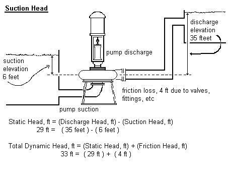
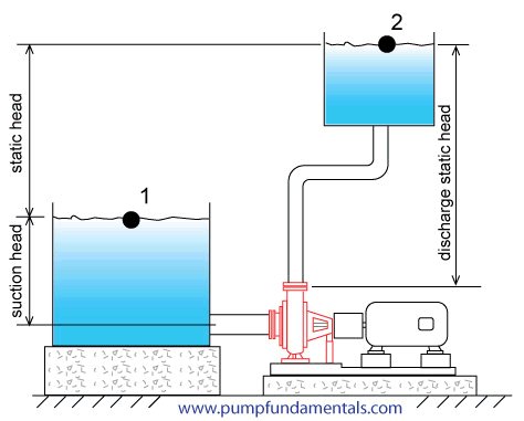
Static Head ဆုိသည္မွာ တြန္းပို့လုိေသာ ေရ ေရာက္ရွိသြားရမည့္ ေဒါင္လုိက္အၿမင့္(vertical distance) ၿဖစ္သည္။
(Static Head, ft) = (Discharge Head, ft) - (Suction Head, ft)
Static Head သည္ Discharge Head ႏွင့္ Suction Head ေပါင္းထားၿခင္းၿဖစ္သည္။
Discharge Head ဆုိသည္မွာ ပန့္၏ Center line ( the pump
datum point ဟုလည္းေခၚသည္။) မွ အၿဖည့္ခံကန္ (receiving tank) ၏
ေရမ်က္နွာၿပင္အထိ ေဒါင္လုိက္တုိင္းထားေသာ အၿမင့္ (verticle distance)
ၿဖစ္သည္။
Suction Head ဆုိသည္မွာ ပန့္၏ Center line ( the pump
datum point ဟုလည္းေခၚသည္။) မွ စုပ္ယူမည့္ ေရမ်က္နွာၿပင္အထိ
ေဒါင္လုိက္တုိင္းထားေသာ အၿမင့္ (verticle distance) ၿဖစ္သည္။
စုပ္ယူမည့္ ေရမ်က္နွာၿပင္သည္ပန့္ the pump datum point ၏ အထက္တစ္ေနရာတြင္လည္းၿဖစ္လွ်င္ Positive Suction Head ဟုသတ္မွတ္သည္။
သို့မဟုတ္ စုပ္ယူမည့္ ေရမ်က္နွာၿပင္သည္ပန့္ the pump
datum point ၏ အနိမ့္တစ္ေနရာတြင္လည္းၿဖစ္လွ်င္ Negative Suction Head
ဟုသတ္မွတ္သည္။
ဥပမာ ၁
ေၿမၿပင္ေပၚတြင္ရွိေသာ ေရကန္တစ္လံုးမွာ အၿမင့္တူညီေသာ
ေနာက္ေရကန္တစ္လံုးအတြင္းသို့ပန့္ၿဖင့္ေမာင္းထည့္လွ်င္ထုိ ပန့္၏ static head
မွာ သုည ၿဖစ္သည္။ တနည္း static head မရွိေပ။ အဘယ္ေၾကာင့္ဆုိေသာ
ေဒါင္လုိက္အၿမင့္(vertical distance) မရွိေသာေၾကာင့္ၿဖစ္သည္။
ဥပမာ၂
ေၿမၿပင္ေပၚတြင္ရွိေသာ ေရကန္တစ္လံုးမွာ ၁၅
ေပအၿမင့္တြင္ရွိေသာ ေရစင္တစ္ခုအတြင္းရွိေရကန္ထဲသို့
ပန့္ၿဖင့္ေမာင္းထည့္လွ်င္ ထုိပန့္၏ static head မွာ 15 ft Head ၿဖစ္သည္။
စုပ္ယူမည့္ ေရမ်က္နွာၿပင္သည္ ပန့္ the pump datum point ႏွင့္
အၿမင့္တူေသာေနရာတြင္ရွိေသာေၾကာင့္ static head (= 0) မရွိေပ။ Suction Head
မရွိေသာေၾကာင့္ static headသည္ Discharge head15 ft ႏွင့္တူညီသည္။
ဥပမာ ၃
 အနက္ ၅ ေပရွိေသာ ေရတြင္းတစ္ခုအတြင္းမွ
ေရကို၁၂၅ေပအၿမင့္တြင္ရွိေသာ ေရစင္တစ္ခုအတြင္းရွိေရကန္ထဲသို့
ပန့္ၿဖင့္ေမာင္းထည့္လွ်င္ ထုိပန့္၏ static head မွာ (125, ft) - (-5, ft) =
130ft Head ၿဖစ္သည္။
စုပ္ယူမည့္ ေရမ်က္နွာၿပင္သည္ ပန့္ the pump datum
point ထက္အနိမ့္ ၁၀ေပ ေနရာတြင္ရွိေသာေၾကာင့္ Negative Suction Head (-5ft)
ၿဖစ္သည္။
(Static Head, ft) = (Discharge Head, ft) - (Suction Head, ft) = (125, ft) - (-5, ft) = 130ft
ဥပမာ ၄
အၿမင့္ ၁၅ ေပရွိေသာ ေရကန္တစ္ခုအတြင္းမွ ေရကို
၂၅ေပအၿမင့္တြင္ရွိေသာ ေရစင္တစ္ခုအတြင္းရွိေရကန္ထဲသို့
ပန့္ၿဖင့္ေမာင္းထည့္လွ်င္ ထုိပန့္၏ static head မွာ (25, ft) - (+15, ft) =
10ft Head ၿဖစ္သည္။
စုပ္ယူမည့္ ေရမ်က္နွာၿပင္သည္ ပန့္ the pump datum
point ထက္အၿမင့္ ၁၅ေပ ေနရာတြင္ရွိေသာေၾကာင့္ Positive Suction Head (+15ft)
ၿဖစ္သည္။
(Static Head, ft) = (Discharge Head, ft) - (Suction Head, ft) = (25, ft) - (+15, ft) = 10ft
အနက္ ၅ ေပရွိေသာ ေရတြင္းတစ္ခုအတြင္းမွ
ေရကို၁၂၅ေပအၿမင့္တြင္ရွိေသာ ေရစင္တစ္ခုအတြင္းရွိေရကန္ထဲသို့
ပန့္ၿဖင့္ေမာင္းထည့္လွ်င္ ထုိပန့္၏ static head မွာ (125, ft) - (-5, ft) =
130ft Head ၿဖစ္သည္။
စုပ္ယူမည့္ ေရမ်က္နွာၿပင္သည္ ပန့္ the pump datum
point ထက္အနိမ့္ ၁၀ေပ ေနရာတြင္ရွိေသာေၾကာင့္ Negative Suction Head (-5ft)
ၿဖစ္သည္။
(Static Head, ft) = (Discharge Head, ft) - (Suction Head, ft) = (125, ft) - (-5, ft) = 130ft
ဥပမာ ၄
အၿမင့္ ၁၅ ေပရွိေသာ ေရကန္တစ္ခုအတြင္းမွ ေရကို
၂၅ေပအၿမင့္တြင္ရွိေသာ ေရစင္တစ္ခုအတြင္းရွိေရကန္ထဲသို့
ပန့္ၿဖင့္ေမာင္းထည့္လွ်င္ ထုိပန့္၏ static head မွာ (25, ft) - (+15, ft) =
10ft Head ၿဖစ္သည္။
စုပ္ယူမည့္ ေရမ်က္နွာၿပင္သည္ ပန့္ the pump datum
point ထက္အၿမင့္ ၁၅ေပ ေနရာတြင္ရွိေသာေၾကာင့္ Positive Suction Head (+15ft)
ၿဖစ္သည္။
(Static Head, ft) = (Discharge Head, ft) - (Suction Head, ft) = (25, ft) - (+15, ft) = 10ft
 ဥပမာ၅
Cooling Tower တစ္လံုး ၏ Hot water Basin သည္ ပန့္ the
pump datum point ထက္ ၁၅ ေပအၿမင့္တြင္ရွိသည္။ Cooling Tower တစ္လံုး ၏
Cool water Basin သည္ ပန့္ the pump datum point ထက္ ၁၀
ေပအၿမင့္တြင္ရွိလွ်င္ ထုိ Cooling Tower တြင္တပ္ဆင္ထားေသာ Condenser Water
Pump ၏ Static Head သည္မည္မွ်ၿဖစ္မည္နည္း။
Condenser Water Pump သည္ Cool water Basin မွ ေရကို
စုပ္ယူ၍ Chiller မွတဆင့္ Hot water Basinအထိေရာက္ေအာင္တြန္းပို့သည္။
ထုိေၾကာင့္ စုပ္ယူမည့္ ေရမ်က္နွာၿပင္သည္ ပန့္ the pump datum point
ထက္အၿမင့္ ၁၀ေပ ေနရာတြင္ရွိေသာေၾကာင့္ Positive Suction Head (+10ft)
ၿဖစ္သည္။ Discharge Head မွာ 15ft ၿဖစ္သည္။
(Static Head, ft) = (Discharge Head, ft) - (Suction Head, ft) = (15, ft) - (+10, ft) = 5ft
ဥပမာ ၆
ဥပမာ၅
Cooling Tower တစ္လံုး ၏ Hot water Basin သည္ ပန့္ the
pump datum point ထက္ ၁၅ ေပအၿမင့္တြင္ရွိသည္။ Cooling Tower တစ္လံုး ၏
Cool water Basin သည္ ပန့္ the pump datum point ထက္ ၁၀
ေပအၿမင့္တြင္ရွိလွ်င္ ထုိ Cooling Tower တြင္တပ္ဆင္ထားေသာ Condenser Water
Pump ၏ Static Head သည္မည္မွ်ၿဖစ္မည္နည္း။
Condenser Water Pump သည္ Cool water Basin မွ ေရကို
စုပ္ယူ၍ Chiller မွတဆင့္ Hot water Basinအထိေရာက္ေအာင္တြန္းပို့သည္။
ထုိေၾကာင့္ စုပ္ယူမည့္ ေရမ်က္နွာၿပင္သည္ ပန့္ the pump datum point
ထက္အၿမင့္ ၁၀ေပ ေနရာတြင္ရွိေသာေၾကာင့္ Positive Suction Head (+10ft)
ၿဖစ္သည္။ Discharge Head မွာ 15ft ၿဖစ္သည္။
(Static Head, ft) = (Discharge Head, ft) - (Suction Head, ft) = (15, ft) - (+10, ft) = 5ft
ဥပမာ ၆
 ဥပမာ ၇
Friction Head
Piping system တစ္ခုအတြင္းတြင္ မည္သည့္ အရည္တစ္မ်ိဳး
(liquid) စီးဆင္းပါက(flow) ထုိအရည္၏ fluid friction ေၾကာင့္ head or
pressure losses ၿဖစ္ေပၚသည္။ ထုိအၿပင္ fluid သည္ piping system
အတြင္းတြင္အသံုးၿပဳထာေသာ valves, strainers, and bends တုိ့မွ
ၿဖစ္ေပၚလာေသာ ခုခံအား (resistance) မ်ား မွ လည္း ၿဖစ္ေပၚလာသည္။
The friction losses မ်ားသည္ ပိုက္ material အမ်ိဳးအစား
(the pipe material), ပိုက္အရွည္ (length of the piping),
ပိုက္အတြင္းတြင္ အရည္၏သြားနွုန္း (fluid velocity) ႏွင့္ အရည္၏
properties (properties of the fluid) တုိ့ၿဖစ္သည္။ ထုိေၾကာင့္ ေရ(water)
ကဲ့သုိ့အရည္မ်ိဳးသည္ ကို အသံုးၿပဳသည္ water distribution system မ်ားတြင္
minimizing pipe length
and reducing flow velocity (increasing pipe diameter) တုိ့ၿဖင့္ friction losses ကို ေလွ်ာ့ခ်နုိင္သည္။
Major Head Loss - head loss or pressure loss - due to friction in pipes and ducts.
Minor Head Loss - head loss or pressure loss - due to components as valves, bends, tees and the like in the pipe or duct system
ပန္ ့တစ္လံုးကို မေရြးခ်ယ္မွီ System အတြက္ လုိအပ္ေသာ flow rate and Total dynamic Head (TDH) ကို သိရွိရန္လုိအပ္သည္။
Head ဆုိသည္မွာ လုိအပ္ေသာ flow amount စီးဆင္းသြားရန္အတြက္ သို့ စီးဆင္းသြားေၾကာင့္ၿဖစ္ေပၚလာေသာ ခုခံအား(resistance) ၿဖစ္သည္။
ပန့္တစ္လံုး၏ ေအာက္ output သည္ 20 head feet ရွိသည္ဟုသည္မွာ ထုိပန့္ မွထြက္လာသည္ ေရကို ေလထဲသို. တည္မတ္စြာလႊတ္လုိက္လွ်င္ ေပ၂၀ အၿမင့္သုိ့ေရာက္သည္ဟုဆုိလုိသည္။
Friction Head
and reducing flow velocity (increasing pipe diameter) တုိ့ၿဖင့္ friction losses ကို ေလွ်ာ့ခ်နုိင္သည္။
| Friction losses ဟုလည္း ေခၚသည္ Major Head Losses ဟုလည္း ေခၚသည္။ |
Dynamic losses ဟုလည္း ေခၚသည္။ Minor Head Losses ဟုလည္း ေခၚသည္။ |
| Pipe Size (flow velocity) Pipe Length Pipe material |
changes in flow area (Velocity) Change in Flow Direction Obstructions |
Friction Head = Friction losses သို့ Major Head Losses + Dynamic losses သုိ့ Minor Head Losses
Piping systems မ်ားတြင္ တပ္ဆင္ထားေသာ အမ်ိဳးမ်ိဳးေသာ
fittings and devices မ်ားေၾကာင့္ၿဖစ္လာေသာ The Dynamic losses သို့ Minor
Head Losses မ်ားၿဖစ္ေပၚသည္။ ထို losses မ်ားပမာဏသည္ fittings and devices
မ်ား၏ ဒီဇုိင္းေပၚတြင္မူတည္သည္။ ထုိေၾကာင့္ flow velocity တစ္ခု အတြက္
ဘားပံုစံ(types of valves) မ်ားေၿပာင္းလွ်င္ေၿပာင္းသလုိ
၄င္းတုိ့ႏွင့္သက္ဆုိင္ေသာDynamic losses သို့ Minor Head Losses
မ်ားမ်ားလည္းလုိက္၍ေၿပာင္းလဲသည္။ ထုိေၾကာင့္ ဘားပံုစံ(types of valves)
မ်ားကို သင့္ေလွ်ာ္ေသာ applications အတြက္ စနစ္တက်ေရႊးခ်ယ္တတ္ရန္လုိအပ္သည္။
ဥပမာအားၿဖင့္ globe ဘားသည္ (globe
type valves) chilled water and condenser water piping systems မ်ားတြင္
အဖြင့္အပိတ္(isolation) မ်ားလုပ္ရန္အတြက္ အမ်ားဆံုးအသံုးၿပဳေလ့ရွိသည္။ ထုိ
globe ဘားသည္ လံုးဝပြင့္ေနသည့္အခါ (fully open) မ်ိဳးတြင္ေတာင္မွ
high-pressure drop ရွိသည္။ အဘယ္ေၾကာင့္ဆိုေသာ္ globe ဘား၏
တည္ေဆာက္ပံုေၾကာင့္ စီဆင္းမွဳ၏ ဦးတည္ရာေၿပာင္းလဲသြားေသာေၾကာင့္ၿဖစ္သည္။
(to the change in direction the flow). Butterfly valves သည္
လံုးဝပြင့္ေနသည့္အခါ (fully open) တြင္ အနည္းငယ္ေသာ သို့ မေၿပာပေလာက္ေသာ
resistance ကိုသာ ၿဖစ္ေစသည္။
Total dynamic head (TDH) - ဆုိသည္မွာ static head,
Friction losses(Major Head Losses) ႏွင့္ Dynamic losses (Minor Head
Losses) တုိ့ေပါင္းထားၿခင္းပင္ၿဖစ္သည္။ TDH ကို the horsepower
calculations အတြက္လည္းသံုးသည္။
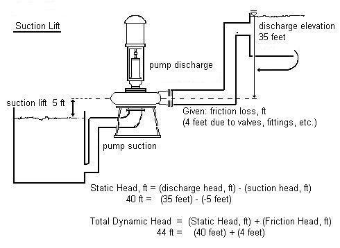
EXAMPLE: The influent pump discharges into a channel where the liquid level is 14 feet above the pump datum line. The pump draws its suction from a wet well, whose water surface is 5 feet above the pump. The friction head is 5.6 ft.
Determine the Static Head, in feet.
Static Head, ft = (Discharge Elev, ft) - (Suction Elev., ft)
Static Head, ft = (14 ft) - (5 ft) = 9 ft Static Head
Calculate the Total Dynamic Head (TDH), in feet.
TDH = (Static Head, ft) + (Friction Head, ft)
TDH = (9 ft) + ( 5.6 ft) = 14.6 ft TDH
PROBLEM: The influent pump discharges into the grit chamber, where the liquid level is 8 feet above the pump datum line. The pump draws its suction from a wet well, whose water surface is 2 feet above the pump. The friction head is estimated at 2.5 ft.
Determine the Static Head, in feet. (Ans: 6 ft)
Calculate the Total Dynamic Head (TDH), in feet. (Ans: 8.5 ft)
PROBLEM: The polymer makeup pump discharges into the solution tank, where the liquid level is 8 feet above the pump datum line. The pump draws its suction from a sump, whose water surface is 2 feet above the pump. The friction head is 1.5 ft.
Determine the Static Head, in feet. (Ans: 6 ft)
Calculate the Total Dynamic Head (TDH), in feet. (Ans: 7.5 ft)
SUCTION LIFT & TDH PROBLEMS
EXAMPLE: The influent pump discharges into a channel where the liquid level is 14 feet above the pump datum line. The pump draws its suction from a wet well, whose water surface is 3 feet BELOW the pump. The friction head is 6 ft.
Determine the Static Head, in feet.
Static Head, ft = (Discharge Elev, ft) - (Suction Elev., ft)
Static Head, ft = (14 ft) - (-3 ft) = 17 ft Static Head
Calculate the Total Dynamic Head (TDH), in feet.
TDH = (Static Head, ft) + (Friction Head, ft)
TDH = (17 ft) + (6 ft) = 23 ft TDH
PROBLEM: The influent pump discharges into the grit chamber, where the liquid level is 8 feet above the pump datum line. The pump draws its suction from a wet well, whose water surface is 2 feet below the pump. The friction head is estimated at 2.5 ft.
Determine the Static Head, in feet. (Ans: 10 ft)
Calculate the Total Head (TDH), in feet. (Ans: 12.5 ft)
PROBLEM: The raw water pump discharges into the sand trap, where the liquid level is 18 feet above the pump datum line. The pump draws its suction from a sump in the reservoir, whose water surface is 2 feet below the pump. The friction head is estimated at 4 ft.
Determine the Static Head, in feet. (Ans: 20 ft)
Calculate the Total Dynamic Head (TDH), in feet. (Ans: 24 ft)
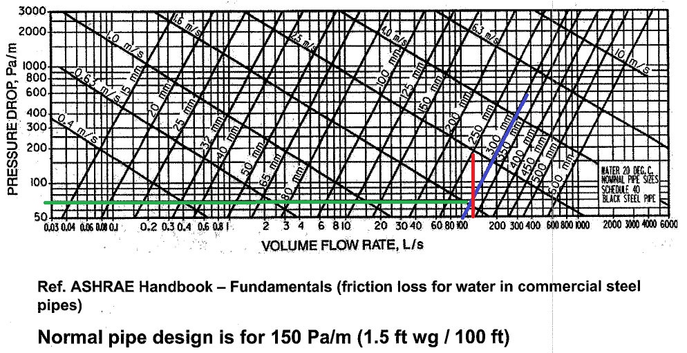
Pump Sizing Example ( Open System)
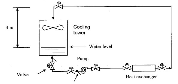
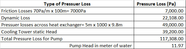
 ဤဥပမာတြင္ Pump Head ကို တြက္ရန္အတြက္ Friction Losses ႏွင့္ Dynamic losses ကိုတစ္မ်ိဳးစီတြက္ၿပီးေပါင္းရန္ၿဖစ္သည္။
Friction Losses သည္ Pipe Size ( Flow Velocity), Pipe Length ႏွင့္ Pipe material တုိ့ေပၚတြင္မူတည္သည္။
Dynamic losses သည္ changes in flow area (Velocity), chages in flow direction ႏွင့္ obstructions တုိ့ေပၚတြင္မူတည္သည္။
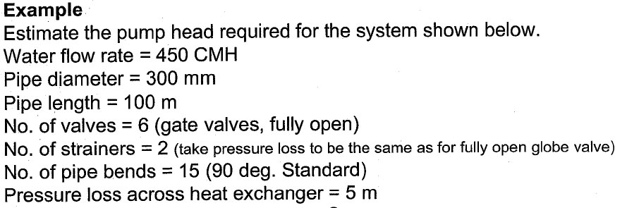
Friction Losses ကို ASHRAE Handbook - Fundamental ၏
Friction loss for water in commercial steel pipe Chart
မွဖတ္ယူသည့္နည္းၿဖင့္တြက္ယူရန္ၿဖစ္သည္။ Formul ႏွင့္လည္းတြက္ယူနုိင္သည္။
က) Pipe Diameter လုိင္းသည္ ညာဘက္သုိ့ေစာင္းေနေသာ
ကန့္လန့္ၿဖတ္လုိင္းမ်ားၿဖစ္သည္။ Pipe Diameter = 300mm လုိင္းသည္
အၿပာလုိင္းၿဖစ္သည္။
ခ) Water Flow rate = 450 CMH = 125 L/s - Volume Flow
Rate (L/s) လုိင္းသည္ ေဒါင္လုိက္လုိင္းမ်ားၿဖစ္သည္။ Water Flow rate = 450
CMH = 125 L/s လုိင္းသည္ အနီေရာင္လုိင္းၿဖစ္သည္။
ထုိလုိင္းႏွစ္လုိင္းၿဖတ္မွတ္မွ point တစ္ခုကိုရသည္။ ထုိ
point မွ Pressure Drop ( အလ်ားလိုက္အစိမ္းေရာင္လုိင္းမွ) 70Pa/m Pressure
Drop ကို ရသည္။ Pipe Length = 100m x 70Pa/m = 7,000Pa သည္ Friction Losses.
ထုိ 300m ပုိက္ထဲတြင္ 125 L/s - Volume Flow Rate
သြားလွ်င္ Velocity မွာ 1.7m/sec ၿဖစ္သည္။ Chart ေပၚမွ ဘယ္ဘက္သို့ ေစာင္း
ေစာင္းေနေသာ ကန့္လန့္ၿဖတ္လုိင္း (Velocity လုိင္းမွ)ဖတ္ယူနုိင္သည္။
.
ဤဥပမာတြင္ Pump Head ကို တြက္ရန္အတြက္ Friction Losses ႏွင့္ Dynamic losses ကိုတစ္မ်ိဳးစီတြက္ၿပီးေပါင္းရန္ၿဖစ္သည္။
Friction Losses သည္ Pipe Size ( Flow Velocity), Pipe Length ႏွင့္ Pipe material တုိ့ေပၚတြင္မူတည္သည္။
Dynamic losses သည္ changes in flow area (Velocity), chages in flow direction ႏွင့္ obstructions တုိ့ေပၚတြင္မူတည္သည္။
Friction Losses ကို ASHRAE Handbook - Fundamental ၏
Friction loss for water in commercial steel pipe Chart
မွဖတ္ယူသည့္နည္းၿဖင့္တြက္ယူရန္ၿဖစ္သည္။ Formul ႏွင့္လည္းတြက္ယူနုိင္သည္။
က) Pipe Diameter လုိင္းသည္ ညာဘက္သုိ့ေစာင္းေနေသာ
ကန့္လန့္ၿဖတ္လုိင္းမ်ားၿဖစ္သည္။ Pipe Diameter = 300mm လုိင္းသည္
အၿပာလုိင္းၿဖစ္သည္။
ခ) Water Flow rate = 450 CMH = 125 L/s - Volume Flow
Rate (L/s) လုိင္းသည္ ေဒါင္လုိက္လုိင္းမ်ားၿဖစ္သည္။ Water Flow rate = 450
CMH = 125 L/s လုိင္းသည္ အနီေရာင္လုိင္းၿဖစ္သည္။
ထုိလုိင္းႏွစ္လုိင္းၿဖတ္မွတ္မွ point တစ္ခုကိုရသည္။ ထုိ
point မွ Pressure Drop ( အလ်ားလိုက္အစိမ္းေရာင္လုိင္းမွ) 70Pa/m Pressure
Drop ကို ရသည္။ Pipe Length = 100m x 70Pa/m = 7,000Pa သည္ Friction Losses.
ထုိ 300m ပုိက္ထဲတြင္ 125 L/s - Volume Flow Rate
သြားလွ်င္ Velocity မွာ 1.7m/sec ၿဖစ္သည္။ Chart ေပၚမွ ဘယ္ဘက္သို့ ေစာင္း
ေစာင္းေနေသာ ကန့္လန့္ၿဖတ္လုိင္း (Velocity လုိင္းမွ)ဖတ္ယူနုိင္သည္။
.
 Dynamic losses
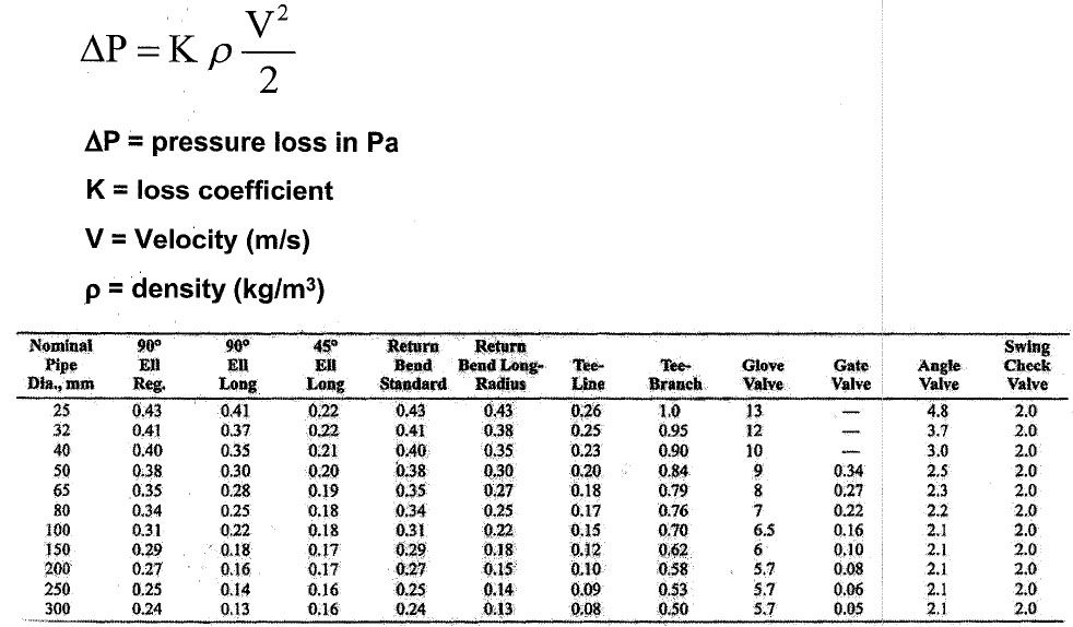
Number of Valve = 6 ( Gate Valve, fully open)
Number of Stariner = 2 ( take pressuer loss to be the same as for fully open globe valve)
Number of pipe bends = 15 ( 90 Degree Standard elbow)
Dynamic losses
Number of Valve = 6 ( Gate Valve, fully open)
Number of Stariner = 2 ( take pressuer loss to be the same as for fully open globe valve)
Number of pipe bends = 15 ( 90 Degree Standard elbow)
 Number of Valve = 6 ( Gate Valve, fully open)
fully opened gate valve ၏ K တန္ဘိုး မွာ အထက္ပါ ဇယားမွာ 300mm ပုိက္ ၾကည့္လွ်င္ 0.05 ၿဖစ္သည္။
Pressure drop for fully opened gate valve = K x density of water x Velocity x Velociyt / 2
Pressure drop for fully opened gate valve = 0.05 x 1000 kg/ cu m x 1.7 m/s x 1.7 m/s/ 2 = 72.25Pa/Gate Valve
For 6 Valves x 72.25Pa/Gate Valve = 433.50Pa
Number of Valve = 6 ( Gate Valve, fully open)
fully opened gate valve ၏ K တန္ဘိုး မွာ အထက္ပါ ဇယားမွာ 300mm ပုိက္ ၾကည့္လွ်င္ 0.05 ၿဖစ္သည္။
Pressure drop for fully opened gate valve = K x density of water x Velocity x Velociyt / 2
Pressure drop for fully opened gate valve = 0.05 x 1000 kg/ cu m x 1.7 m/s x 1.7 m/s/ 2 = 72.25Pa/Gate Valve
For 6 Valves x 72.25Pa/Gate Valve = 433.50Pa
Number of Stariner = 2 ( take pressuer loss to be the same as for fully open globe valve)
fully opened globe valve ၏ K တန္ဘိုး မွာ အထက္ပါ ဇယားမွာ 300mm ပုိက္ ၾကည့္လွ်င္ 0.05 ၿဖစ္သည္။
Pressure drop for fully opened globe valve = K x density of water x Velocity x Velociyt / 2
Pressure drop for fully opened globe valve = 5.7 x 1000 kg/ cu m x 1.7 m/s x 1.7 m/s/ 2 = 8236.5Pa
For 2 Strainer x 8236.5Pa = 16473.00 Pa
Number of pipe bends = 15 ( 90 Degree Standard elbow)
fully opened globe valve ၏ K တန္ဘိုး မွာ အထက္ပါ ဇယားမွာ 300mm ပုိက္ ၾကည့္လွ်င္ 0.05 ၿဖစ္သည္။
Pressure drop for fully opened globe valve = K x density of water x Velocity x Velociyt / 2
Pressure drop for fully opened globe valve = 5.7 x 1000 kg/ cu m x 1.7 m/s x 1.7 m/s/ 2 = 346.8 Pa/ elbow
For 15 elbow x 346.8 Pa/ elbow = 5202 Pa

Pressuer losses across heat exchanger= High of Water (H) x Desity of Water x G = 5m x 1000 x 9.8m = 49,000 Pa
Cooling Tower Static Head = High of Water (H) x Desity of Water x G = 4m x 1000 x 9.8m = 39,200 Pa
ပုစၦာတြင္ pipe diameter မေပးထားခဲ့လွ်င္
က) Chart မွဖတ္ယူသည့္နည္းၿဖင့္တြက္ယူရန္ Desing Pressure
Drop (သို့ Friction loss) ကို ပိုက္ ၁မီတာလွ်င္ 150 Pa ( 150Pa/m) ကို
အေၿခခံ၍တြက္ခ်က္မည္ၿဖစ္သည္။ 150Pa/m Desing Pressure Drop သည္
(1.5ft/100ft) တပ္ဆင္ထားသည္ ပိုက္100ေပလွ်င္ 1.5ft of water Pressure drop
ႏွင့္တူညီသည္။
ခ) Water Flow rate = 450 CMH = 125 L/s
ဂ) Pressure Drop လုိင္းသည္ အလ်ားလုိက္လုိင္းမ်ားၿဖစ္သည္။ Volume Flow Rate (L/s) လုိင္းသည္ ေဒါင္လုိက္လုိင္းမ်ားၿဖစ္သည္။ 150Pa/m
ကိုအလ်ားလုိက္လုိင္းမွ 125 L/sကိုေဒါင္လုိက္လုိင္းမွ Chart ေပၚမွာဖတ္လွ်င္
pipe diameter ကိုရရွိနုိင္သည္။
Type of Pumps
air-conditioning systems တြင္ Chilled Water Circut and condenser water Circuit မ်ားအတြက္ ပန့္မ်ားလုိအပ္သည္။
chilled water and hot water (heating) systems
မ်ားတြင္, ပန့္မ်ားကို chilled water and hot water မ်ားလွည့္ပတ္ရန္အတြက္
အသံုးၿပဳသည္။ Chiller Water ကို Chiller အတြင္းမွ AHUမ်ားႏွင့္ FCU
မ်ားသို့ေရာက္ေအာင္၊ ထုိမွတဆင့္ cooling Coil မ်ားကိုိၿဖတ္ကာ Chiller
ဆီသုိ့ၿပန္ေရာက္ရန္ အတြက္ ပန့္မ်ားက တြန္းပို့ေပးရသည္။ Chilled Water
Circut ကို Closed System ဟုေခၚသည္။
ထုိနည္းတူစြာပင္ condenser cooling systems တြင္
Condenser Water Pump မ်ားသည္ Condenser Water ကို Chiller အတြင္းမွ
Cooling Tower မ်ားသို့ေရာက္ေအာင္၊ ထုိမွတဆင့္ in-fill မ်ားကိုိၿဖတ္ကာ
Chiller ဆီသုိ့ၿပန္ေရာက္ရန္ အတြက္ ပန့္မ်ားက တြန္းပို့ေပးရသည္။ condenser
Water Circut ကို Opened System ဟုေခၚသည္။
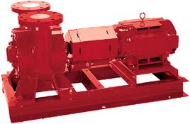
အေဆာက္အဦး၏ ACMV system မ်ားတြင္ Centrifugal pump မ်ားကို တြင္က်ယ္စြာ အသံုးၿပဳၾကသည္။
ပန့္မ်ားကို တပ္ဆင္ထားသည့္ arrangement and
mechanical features တုိ့ကိုလုိက္၍ အမ်ိဳးအစားခြဲၿခားထားသည္။ ေအာက္ပါ
အမ်ိဳးအစားပန့္မ်ားသည္ ACMV system မ်ားတြင္ အသံုးမ်ားေသာ
ပန့္မ်ားၿဖစ္ၾကသည္။
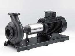
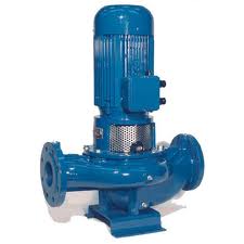
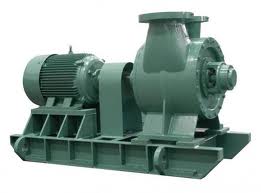
က) End Suction Pump
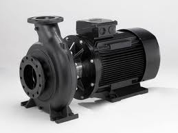
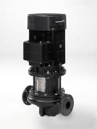
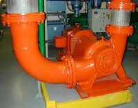
ခ) Inline Pump
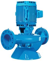
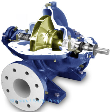
ဂ) Horizontal Split Case Pump
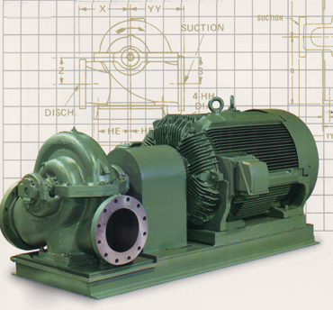
ဃ) Vertical Split Case Pump
End Suction Pump
ေမာ္တာကိုHorizontallyတပ္ဆင္ထားသည္။ေရသည္Horizontalတိုင္းပန့္တြင္းသို့ေရာက္ရွိၿပီး Vetical အတိုင္းၿပန္ထြက္သည္။
|
||
 |
 |
 |
| Inline Pump ေမာ္တာကုိ Verticallyတပ္ဆင္ထားသည္။ေရသည္ Horizontal တိုင္းပန့္တြင္းသို့ေရာက္ရွိၿပီး Horizontal အတိုင္းၿပန္ထြက္သည္။ |
||
 |
 |
 |
Horizontally Split Case Pump
ေမာ္တာကုိHorizontally တပ္ဆင္ထားသည္။ေရသည္ Horizontal တိုင္းပန့္တြင္းသို့ေရာက္ရွိၿပီး Horizontal အတိုင္းၿပန္ထြက္သည္။ |
||
 |
 |
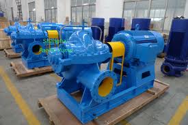 |
| Vertically Split Case Pump ေမာ္တာကုိ Horizontally တပ္ဆင္ထားသည္။ေရသည္ Vertical တိုင္းပန့္တြင္းသို့ေရာက္ရွိၿပီးVertical အတိုင္းၿပန္ထြက္သည္။ |
||
 |
 |
 |
pumping system တုိင္းတြင္ ကြဲၿပားေသာ unique pipe
sizing, pipe length, and fitting မ်ားေၾကာင့္ ကုိယ္ပိုင္ system curve
ကိုယ္စီရွိၾကသည္။ pumping system အတြင္းတြင္ရွိေသာ components (pipe length
ၿဖစ္ေစ Valve, Elbow စေသာ fitting တစ္ခုခု) ေၿပာင္းလဲ လွ်င္ system curve
သည္လည္းေၿပာင္းလဲသြားလိမ့္သည္။ အဘယ္ေၾကာင့္ဆိုေသာ္ စီးဆင္းၿခင္းကို
ခုခံမွဳ (flow resistances) ေၿပာင္းလဲသြားေသာေၾကာင့္ၿဖစ္သည္။
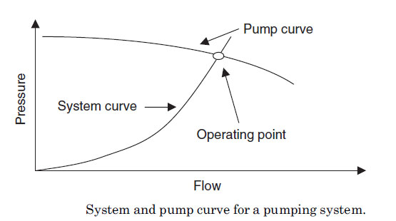
pump curve ဆုိသည္မွာ flow rate and developed pressure
တုိ၏ ဆက္သြယ္ခ်က္ကို ဂရပ္ပံုစံၿဖင့္ေဖာ္ၿပထားၿခင္းၿဖစ္သည္။ pump curve သည္
ပန့္၏ ကြဲၿပားေသာ operating points ( flow နည္းနည္း ႏွင္ Pressure Head
မ်ားမ်ား သို့မဟုတ္ flow မ်ားမ်ားႏွင္ Pressure Head နည္းနည္း ) ကို
ေဖာ္ၿပထားသည္။ Zeor Flow မွ စတင္၍ Full flow အထိ Pressure Head
မ်ားႏွင့္တြဲ၍ေဖာ္ၿပထားသည္။ pump curve သည္ flow rate and developed
pressure တုိအၿပင္ the pump power and operating efficiency
တုိ့၏ဆက္စပ္မွဳမ်ားကိုလည္းသိရွိနုိင္သည္။
pump curves ကို ပန့္ထုပ္လုပ္သူမ်ား (pump manufacturers) ထံမွ ရယူနုိင္သည္။

pump curves မ်ားတြင္ flat curves သုိ့မဟုတ္ steep curves ဟု၍ကြဲၿပားမွဳရွိသည္။
flat curves ကိုပုိင္ဆုိင္ေသာပန့္မ်ားသည္ flow ပမာဏ
မ်ားစြာေၿပာင္းလဲသည့္တုိင္ေအာင္ Pressure သည္ မေၿပာပေလာက္သည့္
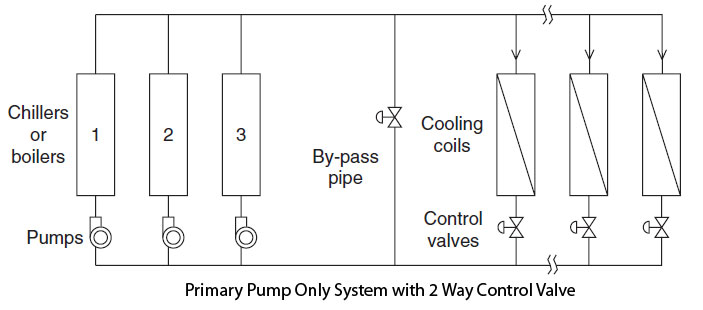
ပမာဏအနည္းငယ္သာေၿပာင္းလဲသည္။ ထုိေၾကာင့္ flat curves
ကိုပုိင္ဆုိင္ေသာပန့္မ်ားသည္ closed systems with modulating 2-way control
valves မ်ားအတြက္အလြန့္သင့္ေလွ်ာ္သည္။ တနည္း Chiller Water pump (closed
system pump) မ်ား အၿဖစ္အလြန္သင့္ေလွ်ာ္သည္။ AHU ႏွင့္ FCU
မ်ားတြင္တပ္ဆင္ထားေသာ modulating 2-way control valves သည္ Building
Cooling Load ေပၚတြင္မွဳတည္၍ လုိအပ္သလုိ လုိအပ္သည့္ %
အတိုင္းအဖြင့္အပိတ္ၿပဳလုပ္ၾကသည္။ ထုိေၾကာင့္ Chiller Water Flow သည္
ေၿပာင္းလဲေသည္။ သို့ေသာ္ Pressure လုိအပ္မွဳက ေၿပာင္းလဲမွဳအလြန္နည္းသည္။
ထိုေၾကာင့္ flat curves ပန့္ သည္ အသင့္ေလွ်ာ္ဆံုးၿဖစ္သည္။
steep curves ကိုပုိင္ဆုိင္ေသာပန့္မ်ားသည္ flow ပမာဏ
၏ေၿပာင္းလဲမွဳအတိုင္း Pressure သည္လုိက္၍ ေၿပာင္းလဲသည္။ Pressure ပမာဏ သည္
လည္း flow ေၿပာင္းလဲသည္အတိုင္းလုိက္ေၿပာင္းလဲသည္။
ထုိေၾကာင့္steep curves ကိုပုိင္ဆုိင္ေသာပန့္မ်ားသည္ constant flow applications such as condenser
water systems serving cooling towers မ်ားအတြက္အလြန့္သင့္ေလွ်ာ္သည္။ တနည္း steep curves ပန့္မ်ားသည္ Condenser Water pump (Opened system pump) မ်ား အၿဖစ္အလြန္သင့္ေလွ်ာ္သည္။
water systems serving cooling towers မ်ားအတြက္အလြန့္သင့္ေလွ်ာ္သည္။ တနည္း steep curves ပန့္မ်ားသည္ Condenser Water pump (Opened system pump) မ်ား အၿဖစ္အလြန္သင့္ေလွ်ာ္သည္။
Pump Head Calculation
Pump head is a measure of energy. The units of energy
are expressed in feet or meters. Pump head သည္ စြမ္းအင္ ေပ သုိ့ မီတာ
(feet or meters)ကိုေဖာ္ၿပသည့္ နည္းတစ္မ်ိဳးၿဖစ္သည္။
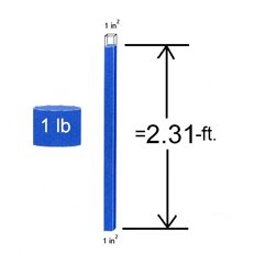
ဖိအားဆုိသည္မွာ a unit of area အေပၚသို့ သက္ေရာက္ေနေသာ
အားပမာဏတစ္ခုၿဖစ္သည္။ ၁ ေပါင္ အားပမာဏ သည္ တစ္လက္မပတ္လည္
ဧရိယာေပၚတြင္သက္ေနေရာက္ေနလွ်င္ ဖိအား a square inch of area, or PSI
ဟုေခၚသည္။ အရပ္သံုးစကားအရ "ေလေပါင္တစ္ေပါင္" အားဟုေၿပာဆုိေလ့ရွိသည္။
သိုေသာ္ 1 PSI ကို (ft of water) ႏွင့္ေဖာ္ၿပမည္ ဆုိလွ်င္ Head (ft. of water)/2.31 = PSI and PSI x 2.31 = Head (feet of water)
pumps မ်ားအတြက္ , 70 feet of head ကို ပို့ေပးနိင္သည့္ Pump သည္ 30 PSI of differential pressure across the pump (i.e., 70 feet/2.31 = 30 PSI.)
pump manufacturer မ်ားသည္ တစ္ညီတညြတ္တည္း “head” သည္
ေဝါဟာရကို အသံုးၿပဳၾကသည္။ Pressure ဟုေၿပာဆုိလွ်င္ pump မွတြန္းနုိင္ေသာ
Pressure သည္ တြန္းပို့မည့္ liquid ၏ the weight (specific gravity)
ႏွင့္ the specific gravity changes with temperature, fluid
အမ်ိဳးအစားႏွင့္ and fluid concentration တုိ့ေပၚတြင္မူတည္သည္။
“head” မ်ားကို တိုင္းတာသည့္ အခါ the center line of the pump မွ တဆင့္ the highest liquid level အထိတိုင္းတာေလ့ရွိသည္။
 |
 |
pump၏ suction ဘက္ႏွင့္ discharge ဘက္တုိ့
resistance in the piping, fittings and valves
တိုေၾကာင့္ၿဖစ္ေပၚလာေသာ Head ကို friction head ဟုေခၚသည္။ any pressure
that might be acting on the liquid in the tanks including atmospheric
pressure ကို " surface pressure head"ဟုေခၚသည္။
the Static discharge head ထဲမွ the Static suction head ကို ႏွတ္လွ်င္ Static Head ကို ရသည္။
System head = total discharge head - total suction head ( တစ္ခါတစ္ရံ Static ဆိုသည့္ စကားလံုးကို friction head မပါဝင္ပါ ဟုသိသာေစရန္ ထည့္သံုးသည္။)
H = hd - hs
The total discharge head is made from three separate heads:
hd = hsd + hpd + hfd
- hd = total discharge head
- hsd = discharge static head (discharge ဘက္တြင္ရွိေသာ Elevation ေၾကာင့္ၿဖစ္သည့္ static head)
- hpd = discharge surface pressure head ( Open System မ်ားတြင္ atmospheric pressure ကို ဆုိလိုသည္။)
- hfd = discharge friction head ( fluid စီးဆင္းမွဳေၾကာင့္ၿဖစ္ေပၚလာေသာ Pressure losses မ်ား)
The total suction head also consists of three separate heads
hs = hss + hps - hfs
- hs = total suction head
- hss = suction static head (suction ဘက္တြင္ရွိေသာ Elevation ေၾကာင့္ၿဖစ္သည့္ static head)
- hps = suction surface pressure head ( Open System မ်ားတြင္ atmospheric pressure ကို ဆုိလိုသည္။)
- hfs = suction friction head ( fluid စီးဆင္းမွဳေၾကာင့္ၿဖစ္ေပၚလာေသာ Pressure losses မ်ား)
"feet of liquid gauge" သို့မဟုတ္ "feet of liquid
absolute" ယူနစ္မ်ား အတုိင္း တြက္ခ်က္မွဳမ်ားၿပဳလုပ္နုိင္သည္။ . "absolute
ဆုိသည္မွာ the gauge reading တြင္ atmospheric pressure (head) ကို
ထည့္ေပါင္းထားၿခင္းၿဖစ္သည္။
ဤဥပမာသည္ Opened System ၿဖစ္သည္။ ACMV system မ်ားတြင္
Cooling Tower သို့ Condenser Water pump ကို တြကပံုမ်ိဳႏွင့္ဆင္တူသည္။
ဤဥပမာ တြင္ The suction head သည္ အႏွဳတ္ (negative) တန္ဘုိးၿဖစ္ၿပီး
Condenser Water pump တြင္ The suction head သည္ အေပါင္းတန္ဘိုးၿဖစ္သည္။
Begin with the total suction head calculation
1. The suction head သည္ အႏွဳတ္ (negative)
တန္ဘုိးၿဖစ္သည္။ The liquid level in the suction tank ၏ the liquid
level သည္ the centerline of the pump ထက္နိမ့္ေနသည္။
hss = - 6 feet ( ပန့္တည္ရွိသည့္ေနရာကို Elevation = 0 ft ဟုယူ၍တြက္ခ်က္ေသာေၾကာင့္ ၿဖစ္သည္။ အႏွဳတ္ သေကၤတမွ စုပ္ယူရမည့္ Fluid ၏ Elevation သည္ Pump ထက္ ၆ေပနိမ့္သည့္ေနရာတြင္ရွိသည့္ဟုဆုိလိုသည္။ )
2. The suction tank သည္ အပြင့္ ပံုစံၿဖစ္သည္ (Open) ,
ထုိေၾကာင့္ the suction surface pressure သည္ atmospheric pressure ႏွင့္
ညီသည္။
hps = 0 feet gauge ( atmospheric pressure သည္ suction ဘက္ႏွင့္ discharge ဘက္တြင္ မွာပါ သက္ေရာက္ေနသည္။ထိုေၾကာင့္ မည့္သည့္တန္ဘိုးထည္တြက္သည္ၿဖစ္ေစ ေက်သြားလိမ့္မည္။)
3. the suction friction head တြက္ယူရန္,
(ဤစာမ်က္ႏွာတြင္ the suction friction head ကို မည့္သို့တြက္ခ်က္သည္
မေဖာ္ၿပပါ။ 4 feet ဟုယူဆ၍တြက္သည္။)
hfs = 4 feet at rated flow ( friction loss calculation မွ ရရွိသည္။ friction loss calculation တြက္နည္းကို ေနာက္ စာမ်က္ႏွာမ်ားတြင္ေဖာ္ၿပမည္)
4. The total suction head သည္ a gauge တန္ဘိုးၿဖစ္သည္။
အဘယ္ေၾကာင့္ဆုိေသာ္atmosphere Pressuer ကို 0
အၿဖစ္တြက္ခ်က္ေသာေၾကာင့္ၿဖစ္သည္။
hs = hss + hps - hfs = -6 + 0 - 4 = -10 feet of liquid gauge at rated flow
The total discharge head calculation
1. The static discharge head is:
hsd = 125 feet ( ပန့္တည္ရွိသည့္ေနရာကို Elevation = 0 ft ဟုယူ၍တြက္ခ်က္ေသာေၾကာင့္ ၿဖစ္သည္။)
2. The discharge tank သည္ အပြင့္ ပံုစံၿဖစ္သည္ (Open) ,
ထုိေၾကာင့္ the suction surface pressure သည္ atmospheric pressure
ႏွင့္ ညီသည္။
hpd = 0 feet, gauge
3. The discharge friction head ကို ၂၅ feet
ဟုယူဆ၍တြက္သည္။discharge friction head သည္ pipe အတြင္းတြင္ရွိေသာ Fluid
Velocity ႏွင့္ Fitting အေရအတြက္တို့ေပၚတြင္မူတည္သည္။
hfd = 25 feet at rated flow
4. The total discharge head is:
hd = hsd + hpd + hfd = 125 + 0 + 25 = 150 feet of liquid gauge at rated flow
The total system head calculation:
H = hd - hs = 150 - (-10)= 160 feet of liquid at rated flow
Note: did you notice that when we subtracted a minus
number (-10) from a positive number (150) we ended up with a positive
160.
vacuum application ႏွင့္သက္ဆုိင္ေသာ ဥပမာ ကို
ဆက္လက္တြက္ခ်က္ပါမည္။ . Pipe friction တန္ဘိုးမ်ားကို Hydraulic Institute
Engineering Data Book မွ ရယူရန္ၿဖစ္သည္။ chart section
Specifications:
1. Transferring 1000 gpm. weak acid from the vacuum
receiver to the storage tank. အက္စစ္ေပ်ာ့မ်ားထည့္ထားသည္ အလံုပိတ္ကန္မွ
တစ္မီနစ္လွ်င္ အက္စစ္ ဂါလံ 1000 တြန္းပို့ရန္ၿဖစ္သည္။
2. Specific Gravity - 0.98 (ထည့္ထားေသာ အက္စစ္ ၏ သိပ္သည္းဆ Specific Gravity မွ 0.98 ၿဖစ္သည္။)
3. Viscosity - equal to water (ပ်စ္ေစးမွဳ Viscosity သည္ ေရ၏ ပ်စ္ေစးမွဳ Viscosity ႏွင့္တူညီသည္။)
4. Piping - All 6" Schedule 40 steel pipe - ပိုက္အမ်ိဳးအစားမ်ားမွာ Schedule 40 အဆင့္ရွိေသာ steel pipe မ်ားၿဖစ္သည္။
5. Discharge piping rises 40 feet vertically above
the pump centerline and then runs 400 feet horizontally. There is one
90° flanged elbow in this line.
Dischargeပိုက္သည္ ပန့္ႏွင့္ေမာ္တာ မွ အထက္ ေပ ၄၀
အၿမင့္တြင္ရွိသည္။ ထုိေနာက္ ေလွာင္ကန္သို့ေရာက္ရန္ ေရၿပင္ညီအတုိင္း ေပ 400
အရွည္ရွိသည္။ 90° flanged elbow တပ္ဆင္ထားသည္။
6. Suction piping has a square edge inlet, four feet
of pipe, one gate valve, and one 90° flanged elbow all of which are 6"
in diameter.
Suction ပိုက္တြင္ a square edge inlet, four feet of
pipe, one gate valve, ႏွင့္ one 90° flanged elbowတပ္ဆင္ထားၿပီး ပိုက္
diameter မွာ ၆ လက္မၿဖစ္သည္။
7.The minimum level in the vacuum receiver မွာ the pump centerlineထက္ ၅ ေပၿမင့္သည္။
8. Vacuum ေလွာင္ကန္ထဲတြင္ရွိေသာ pressure မွာ 20 inches of mercury, vacuum ၿဖစ္သည္။
To calculate suction surface pressure use one of the following formulas:
- inches of mercury x 1.133/ specific gravity = feet of liquid
- pounds per square inch x 2.31/specific gravity = feet of liquid
- Millimeters of mercury / (22.4 x specific gravity) = feet of liquid
the system ကို pump ေနရာ မွ ႏွစ္ပုိင္း ပိုင္း၍ တြက္ခ်က္ပါမည္။
Total suction head calculation
1. The suction side of the system shows a minimum
static head of 5 feet above suction centerline. Therefore, the static
suction head is:
hss = 5 feet
2. Using the first conversion formula, the suction surface pressure is:
hps = -20 Hg x 1.133/ 0.98 = -23.12 feet gauge
3. The suction friction head, hfs, equals the sum of
all the friction losses in the suction line. Friction loss in 6" pipe
at 1000 gpm from table 15 of the Hydraulic Institute Engineering Data
Book, is 6.17 feet per 100 feet of pipe.
in 4 feet of pipe friction loss = 4/100 x 6.17 = 0.3 feet
Friction loss coefficients (K factors) for the inlet,
elbow and valve can be added together and multiplied by the velocity
head:
| 6" Square edge inlet | 0.50 | 32 (a) |
| 6" 90 flanged elbow | 0.29 | 32 (a) |
| 6" Gate valve | 0.11 | 32 (b) |
Total coefficient, K = 0.90
Total friction loss on the suction side is:
hfs = 0.3 + 1.7 = 2.0 feet at 1000 gpm.
4. The total suction head then becomes:
hs = hss + hps - hfs = 5 + (-23.12) - 2.0 = -20.12 feet, gauge at 1000 gpm.
Total discharge head calculation
1. Static discharge head = hsd = 40 feet
2. Discharge surface pressure = hpd = 0 feet gauge
3. Discharge friction head = hfd = sum of the following losses :
Friction loss in 6" pipe at 1000 gpm. from table 15, is 6.17 feet per hundred feet of pipe. In 440 feet of pipe the friction loss = 440/100 x 6.17 = 27.2 feet
Friction loss in 6" elbow:
from table 32 (a), K = 0,29
from table 15, V2/2g = 1.92 at 1000 gpm.
Friction loss = K V2/2g = 0.29 x 1.92 = 0.6 feet
The friction loss in the sudden enlargement at the
end of the discharge line is called the exit loss. In systems of this
type where the area of the discharge tank is very large in comparison
to the area of the discharge pipe, the loss equals V2/2g, as shown in
table 32 (b).
Friction loss at exit = V2/2g = 1.9 feet
The discharge friction head is the sum of the above losses, that is:
hfd = 27.2 + 0.6 + 1.9 = 29.7 feet at 1000 gpm.
4. The total discharge head then becomes:
hd = hsd + hpd + hfd = 40 + 0 + 29.7 = 69.7 feet, gauge at 1000 gpm.
c. Total system head calculation:
H = hd - hs = 69.7 - (-20.2) = 89.9 feet at 1000 gpm
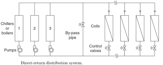
Chilled water/ Hot water Distribution Configuration
ACMV သို့မဟုတ္ HVAC တို တြင္ main piping systems
ႏွစ္မ်ိဳးကို Chilled water/ Hot water circulation လုပ္ရန္ တြင္က်ယ္စြာေတြ
့ရသည္။
က) direct return and
ခ) reverse return systems
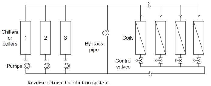
ေအာက္တြင္ေဖာ္ၿပထားေသာ ပံုႏွစ္ခုမွာ direct return ႏွင့္ reverse return systems တို့ၿဖစ္သည္။
direct return ႏွင့္ reverse return systems တုိ့၏ ကြဲၿပားမွဳမွာ the direct return
system ၏ water return pipes သည္ main return header ႏွင့္ တစ္ခုၿခင္းစီ
ပိုက္ဆက္ထားၿခင္း (individually connected)ၿဖစ္ၿပီး reverse return systems
သည္ individual coils မွထြက္လာေသာ Leaving water သည္ အတူတကြ
ေပါင္းၿပီးမွသာ main return header ထဲသို့ဝင္သြားၿခင္းၿဖစ္သည္။
ထုိေၾကာင့္ reverse return systems တြင္ coil တစ္ခုၿခင္းစီမွ circulating pumps အထိ ပိုက္အရွည္ သည္ တူညီၾကသည္။
ထိုကဲ့သုိ့ individual coils တုိင္းတြင္ တူညီေသာ
ပိုက္အရွည္ ရွိၾကေသာေၾကာင့္ coils အားလံုးအတြက္ တူညီေသာ water pressure
drop ကို ၿဖစ္ေစသည္။ ထုိကဲသို့ေသာ reverse return systems
သည္
အလုိေလွ်ာက္ selfbalancing ၿဖစ္ေနၿပီး balancing valves မ်ားတပ္ရန္ မလုိအပ္ေပ။
direct return systems မ်ားတြင္ coil တစ္ခုၿခင္းစီမွ
circulating pumps အထိ ပိုက္အရွည္သည္ coil ၏ တည္ရွိရာေနရာကိုလုိက္၍
မတူညီၾကေပ။ circulating pumps နွင့္ အနီးဆံုးေသာ coil ၏ ပိုက္သည္
အတိုဆံုးၿဖစ္သည္။ ပိုက္အရွည္မတူညီၾကေသာေၾကာင့္ coils တစ္ခုၿခင္းစီ အတြက္
water pressure drop လည္းမတူညီၾကေပ။ ထုိေၾကာင့္ Coil တုိင္း တြင္ balancing
valves မ်ားတပ္ထားရန္လိုအပ္သည္။ branch ပိုက္မ်ားတြင္လည္း balancing
valves မ်ားတပ္ဆင္ရန္လိုအပ္သည္။ ထုိသုိ့မတပ္ဆင္ခဲ့ပါမူ circulating pumps
ႏွင့္ အနီးဆံုး Coil ႏွင့္ အနီးဆံုး branch ပိုက္မ်ားသုိ့ ( water pressure
drop နည္းေသာေၾကာင့္ ) ေရမ်ားသည္ လုိသည္ထက္ပို၍စီးဆင္းသြားလိမ့္မည္။
အေဝးဆံုး Coil ႏွင့္ အေဝးဆံုး branch ပိုက္မ်ား သည္ လုိအပ္သည္ ေရ ပမာဏကို
ရနုိင္လိမ့္မည္မဟုတ္ေပ။
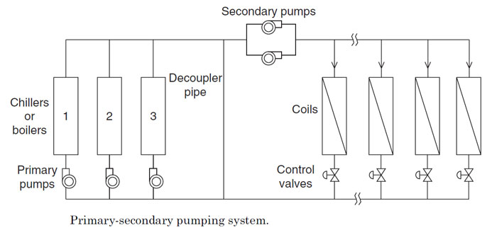
water distribution system တုိ့တြင္ ပန့္ အေရအတြက္ႏွင့္ အသံုးၿပဳပံုကိုမူတည္၍ ကြဲၿပားေသးသည္။
primary-secondary distribution system တြင္ primary pump ႏွင့္ secondary pumps ဟု၍ pump set ႏွစ္မ်ိဳးပါဝင္သည္။
primary pump သည္ ေရ ကို chillers သိုမဟုတ္ boilers
တြန္းပို့သည္ တာဝန္ကို ေဆာင္ရြက္သည္။ (secondary pumps ရွိလွ်င္ Coil
အထိေရာက္ေအာင္တြန္းပို့ရန္မလုိအပ္ေပ).
secondary pumps သည္ ေရကို chillers သိုမဟုတ္ boilers
ဘက္မွ စုပ္ယူ၍ Coil မ်ားအထိေရာက္ေအာင္ေဆာင္ရြက္ရသည္။ primary pump ရွိသည့္
pipe network ဘက္ကို primary Circuit ဟုေခၚၿပီး secondary pumps ရွိသည့္
pipe network ကို secondary Circuit ဟုေခၚသည္။
The primary pumps (primary Circuit)ႏွင့္ secondary
pumps (secondary Circuit)ကို bypass pipe ႏွင့္ hydraulically isolated
ၿဖစ္ေအာင္ခြဲၿခားထားသည္။bypass pipe ကို
decoupler pipe ဟုလည္းေခၚသည္။The secondary
distribution သို့ secondary Circuit ကို direct return သို့ reverse
return System ဟု ႏွစ္မ်ိဳးရွိသည္။
system ၏ water return pipes သည္ main return header ႏွင့္ တစ္ခုၿခင္းစီ ပိုက္ဆက္ထားၿခင္း (individually connected)ၿဖစ္ၿပီး reverse return systems သည္ individual coils မွထြက္လာေသာ Leaving water သည္ အတူတကြ ေပါင္းၿပီးမွသာ main return header ထဲသို့ဝင္သြားၿခင္းၿဖစ္သည္။
 |
 |
decoupler piping အတြင္းတြင္ ေရသည္ ႏွစ္ဘက္စလံုးမွ
စီးဆင္းနုိင္သည္။ မည္သည့္ဘက္ကို စီဆင္းမည္ဆုိသည္မွာ
ထုပ္လုပ္သည့္ေရပမာဏႏွင့္ “production” of chilled or hot water in the
primary circuit (primary flow) ႏွင့္ သံုးစြဲသည့္ ေရပမာဏ the amount of
“consumption” by the building (secondary flow) ေပၚတြင္မူတည္သည္။
primary flow သည္ secondary flow ထက္ပိုမ်ားလွ်င္
decoupler pipe အတြင္းတြင္ ေရ သည္ supply header ဘက္မွ return header
သို့စီဆင္းလိမ့္မည္။
the primary system produces more chilled or hot water
than what the secondary system consumes, the flow of water in the
decoupler pipe will be from supply header to return header.
secondary flow လိုအပ္မွဳသည္ primary flow မွ
ေရထုပ္လုပ္မွဳထက္မ်ားလွ်င္ decoupler pipe အတြင္းတြင္ ေရ သည္ return
header ဘက္မွ supply header သို့စီဆင္းလိမ့္မည္။
On the other hand, if the secondary system requires
more water than that produced by the primary system, the flow of water
in the decoupler pipe will be from return to
supply.
supply.
primary flow ဘက္မွ ေရထုပ္လုပ္မွဳသည္ ေမာင္းသည္ Chiller
capacity ႏွင့္ Chiller အေရအတြက္ေပၚတြင္မူတည္သည္။ ( 1 RT တုိင္းအတြက္ 2.4
USgmp Chilled Water ထုပ္လုပ္သည္။)
primary flow ဘက္မွ ေရလုိအပ္မွဳသည္ building load
ေပၚတြင္မွဳတည္သည္။ ထုိေၾကာင့္ secondary pumps ကို variable speed drives
တပ္ဆင္၍ေမာင္းၾကသည္။
In such primary-secondary systems, hydraulic isolation
allows the secondary pumps to vary the flow (usually using variable
speed drives)
with building load while maintaining a constant flow of water through the primary circuit.
with building load while maintaining a constant flow of water through the primary circuit.

thanks for everything.
ReplyDeleteHello ဆရာ စာတွေက Zawgyi နဲ့ဖြစ်နေလို့ဖတ်မရတော့လို့ပါခင်ဗျာ
ReplyDelete