Chilled Water System Design
Chilled water sytem မ်ားတြင္ အမ်ားဆံုးေတြ ့ရေလ့ရွိသည့္ Circuit ႏွစ္မ်ဳိးမွာ
I) Primay Only Circuit
II) Primary - Secondary Circuit သို့ (Decoupled system) တုိ့ၿဖစ္သည္။
Primary Only Circuit
Primary Chilled Water Circuit တစ္မ်ိဳးတည္းသာ ရွိသည့္ system ကုိ primary only system ဟုေခၚသည္။
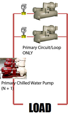 |
Primary Only Circuit/Loop သည္
နားလည္ရန္ ရွင္းလင္းလြယ္ကူသည္။ Chilled water system တစ္ခု တြင္ Chilled
water pump(s) တစ္မ်ိဳးသာ ရွိေသာေၾကာင့္ Chilled Water Circuit လည္း
တစ္မ်ိဳးသာရွိသည္။ ထုိ pump ကို Primary Chilled Water Pump ဟုေခၚသည္။ ထုိ
pump သည္ Chilled water ကုိ AHU / FCU မ်ားဆီသို့ေရာက္ေအာင္တြန္းပိုရသည္။
Secondary Chilled Water Pump ရွိလွ်င္ Primary Chilled Water Pump သည္
Chilled water ကုိ AHU / FCU မ်ားဆီသို့ေရာက္ေအာင္တြန္းပိုရန္မလုိပါ။
ထုိတာဝန္ကုိ Secondary Chilled Water Pump ကေဆာင္ရြက္ေပးသည္။
|
Primay Only Circuit
 |
 |
ပုံတြင္ၿပထားသည့္အတုိင္
Chillers မ်ားကို တပ္ဆင္ထားလွ်င္ Chillers Parallel installation
ၿဖစ္သည္။ဘယ္ဘက္မွပံုတြင္ Primary Chilled Water Pump သည္ ၾကိဳက္သည့္
Chillers ႏွင့္ေမာင္းနုိင္သည္။ ထုိသို့တပ္ဆင္ထားလွ်င္မ်ားေသာအားၿဖင့္
Primary Chilled Water Pump အေရအတြက္သည္ Chiller အေရအတြက္ ၁လံုး သို့ ၂
လံုး ပို၍တပ္ဆင္ထားေလ့ရွိသည္။ ထုိုသို့ Chiller အေရအတြက္ ၁လံုး
ပို၍တပ္ဆင္ထားသည္ကို N+1 configuration ဟုေခၚသည္။
ဘယ္ဘက္မွပံုတြင္ Primary Chilled Water Pump
မ်ားသည္ သက္ဆုိင္သည့္ Chiller တစ္လံုးၿခင္းႏွင့္သာ
ေမာင္းနုိင္သည္။Dedicated Pumps ဟုေခၚသည္။ ထုိသို့တပ္ဆင္ထားလွ်င္ Primary
Chilled Water Pump ႏွင့္ Chiller ကို အတြဲလုိက္ ေမာင္းေလ့၊ ပိတ္ေလ့ရွိသည္။
A pump-and-chiller pair can be turned on and off together.
|
|
Primary - Secondary System သို့ Decoupled system
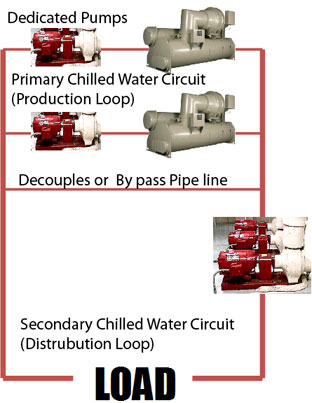 |
ပံုတြင္ၿပထားသည့္အတိုင္း Chiller တစ္လံုးစီအတြက္ Chilled Water Pump တစ္လံုးစီ သီးသန့္တပ္ဆင္ထားသည္။
Production Pump ကုိ Primary Chilled Water Pump
ဟုေခၚသည္။Distrubution ကို Secondary Chilled Water Pump ဟုေခၚသည္။The
production loop မွ Chiller မ်ားေမာင္းသည့္အခါ သတ္မွတ္ထားသည့္ constant
flow of water ၿဖင့္ ေမာင္းေလ့ရွိသည္။ (သို့ေသာ္
( ဥပမာ 500RT (တန္၅၀၀) Chiller တစ္လံုး၏
Standard Chilled water ေရလည္ပတ္နွဳန္း (Standard Chilled water flow
rate ) မွာ 500RT x 2.4GPM = 1,200GPM ၿဖစ္သည္။ ) သို့ေသာ္ the
distribution loop မွ AHU၊FCU ႏွင့္ CRAC unit မ်ားသည္ လုိအပ္သည့္ Cooling
load ေပၚတြင္မူတည္၍ two-way modulating valves ၿဖင့္ Chilled water flow
rate ကုိ ေၿပာင္းလဲတတ္သည္။ The chillers in the production loop receive a
constant flow of water, while the coils in the distribution loop,
controlled by two-way modulating valves, receive a variable flow of
water. ထိုေၾကာင့္ Secondary Chilled Water (Distrubution Loop) Pumps
မ်ားတြင္ လိုအပ္သည့္ Chilled water flow rate
အတုိင္းေမာင္းႏွင္နဳိင္ရန္ (Varible Speed Drive) VSD သို့ Variable
Frequency Dirve (VFD) လုိအပ္သည္။
|
Primary - Secondary System သို့ Decoupled system |
|
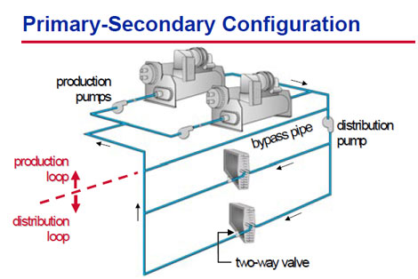 |
Primary Chilled Water Circuit (Production Loop) Secondary Chilled Water Circuit (Distrubution Loop) Primary Chilled Water Circuit ႏွင့္ Secondary Chilled Water Circuit ကို ခြဲထားသည့္ လုိင္းကို Decouples သို့ By pass Pipe line ဟုေခၚသည္။ |
 |
 |
| Dedicated Pumps at Production Loop (Primary Chilled Water Circuit/Loop) | Minifolded Production Pump သို Common Header at Production Loop (Primary Chilled Water Circuit/Loop) |
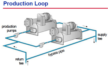
The production pumps သို့ Primary Chilled Water Pump
သည္ ေရကို return tee မွစုပ္ယူ၍ chiller အတြင္းသို့တြန္းပို့သည္။ထုိမွတဆင့္
the supply tee သို့ေရာက္သည္။ ထုိေၾကာင့္ Primary Chilled Water circuit ၏
pressure losses မွာ သိပ္မ်ားေပ။ ထုိေၾကာင့္ Primary Chilled Water Pump ၏
Pump Head မွာ နည္း ေလ့ရွိသည္။ ပန့္ တစ္လံုးစီသည့္ သူႏွင့္သက္ဆုိင္သည့္
chiller ကိုလိုက္၍ေမာင္းသည္။
Primary Chilled Water Circuit ႏွင့္ Secondary Chilled
Water Circuit ႏွစ္မ်ိဳးလံုးရွိသည့္ system ကုိ primary-secondary system
ဟုေခၚသည္။ primary-secondary system တစ္ခုသည္ production loop (Load Side)
အတြက္ ပို flexibility ရွိသည္။
Dedicated Pumps at Production Loop (Primary Chilled Water Circuit/Loop)
Production Loop (Primary Chilled Water Circuit/Loop) ၌ Dedicated Pumps
မ်ားၿဖင့္ ေမာင္းလွ်င္ Chiller မ်ား၏ အမ်ိဳးအစား(type)၊ အရြယ္(size)၊
သက္တမ္း (age)ႏွင့္ ထုပ္လုပ္သူ (manufacturers)တူသည္ၿဖစ္မတူသည္ၿဖစ္ေစ
တပ္ဆင္နုိင္သည္။ အမ်ိဳးအစား(type)၊ အရြယ္(size)၊ သက္တမ္း (age)ႏွင့္
ထုပ္လုပ္သူ (manufacturers)မတူညီသည့္ Chiller မ်ားတြင္ ကြဲၿပားေသာ
(different evaporator pressure drops) ရွိၾကသည္။ ထုိအၿပင္ Dedicated Pumps
ႏွင့္ individual chiller တုိ့သည္အတြဲလုိက္ၿဖစ္ေနေသာေၾကာင့္ Dedicated
Pumps တစ္လုံးပ်က္သြားလွ်င္ သူႏွင့္သက္ဆုိင္သည့္ chiller လည္း မေမာင္း
နုိင္ေတာ့ေပ။
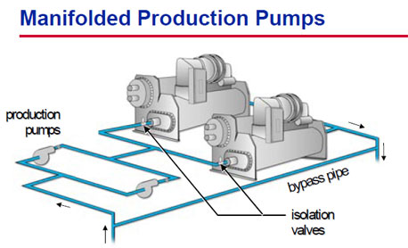
Minifolded Production Pump သို Common Header at Production Loop (Primary Chilled Water Circuit/Loop)
Production Loop (Primary Chilled Water Circuit/Loop)
တြင္ Common Header ၿဖင့္ ပန့္မ်ားကိုတပ္ဆင္ထားၿခင္းသည္ chiller
အမ်ိဳးအစား(type)၊ အရြယ္(size)၊ သက္တမ္း (age)ႏွင့္ ထုပ္လုပ္သူ
(manufacturers)ကို လုိက္၍ system complexity မ်ားသည္။ သို့ေသာ္ greater
redundancy ရွိသည္။ ၾကိဳက္သည့္ Chiller ႏွင့္ သင့္ေလွ်ာ္သည့္ ပန့္ကုိ
ေရႊးခ်ယ္ေမာင္းႏွင္နုိင္သည္။ ပန့္ပ်က္ေသာေၾကာင့္ Chiller
ကိုမေမာင္းနုိင္သည့္အေၿခေနမ်ိဳးမၾကံဳေတြနုိင္။ သို့ေသာ္ Primary Chilled
Water သည္ Common Header မွ တဆင့္(ပန့္မွတုိက္ရုိက္မဟုတ္ဘဲ) Chiller
အတြင္းသုိ့စီဝင္ေသာေၾကာင့္ Chiller တုိင္းတြင္ မွန္ကန္ေသာ ေရလည္ပတ္နွန္း
(rigth amount chilled water flow rate)ရ ရွိရန္ေရးၾကီသည္။ ထုိသိုရရွိရန္
balancing valve သို့ Constant Flow valve မ်ားကို အသံုးၿပဳနုိင္သည္။
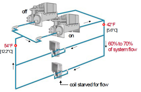
Common Header ၿဖင့္ ပန့္မ်ား၏ ၿပႆနာတစ္မ်ိဳးမွာ
ေရလည္ပတ္နွန္း မတည္ၿငိမ္မူၿဖစ္သည္။ Chiller ၁လံုး သို့ ၂ လံုးေမာင္းေနစဥ္
ေနာက္ထပ္Chiller တစ္လံုးေမာင္းရန္လုိအပ္ပါက isolation valve ကို
အရင္ဖြင့္ရသည္။ ထုိအခိုက္အတန့္တြင္ လက္ရွိေမာင္းေနသည္ Chiller မ်ားမွ
ေရလည္ပတ္နွန္း (chilled water flow rate) သည္ ၂၀% မွ ၅၀% အထိ Chiller
အရြယ္အစား(size)ကို လုိက္၍က်ဆင္းနုိင္သည္။ထုိအခ်ိန္တြင္ ေမာင္းရမည့္ပန့္သည္
ေမာင္းခါစၿဖစ္ေသာေၾကာင့္ Full Speed သို့ မေရာက္နုိင္ေသးေပ။ isolation
valve ကို အရင္မဖြင့္ဘဲ ပန့္ကုိအရင္ေမာင္းပါက လက္ရွိေမာင္းေနသည္ Chiller
မ်ားမွ ေရလည္ပတ္နွန္း (chilled water flow rate) သည္ၿမင့္တက္သြားလိမ့္မည္။
ထုိအခါ water hammer ၿပႆနာကို ၾကံဳေတြနုိင္သည္။
The drawback of manifolding production pumps is that
the chiller flows become hydraulically coupled again. If an isolation
valve is opened before a pump is
started, flow through the operating chillers will drop suddenly, causing potential control instability. If a pump is started before a valve is open, the
operating chillers will see a momentary flow increase, causing control instability or water hammer.
started, flow through the operating chillers will drop suddenly, causing potential control instability. If a pump is started before a valve is open, the
operating chillers will see a momentary flow increase, causing control instability or water hammer.
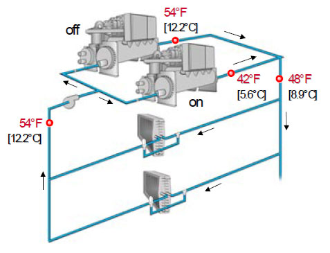
Chiller မ်ား၏ Control Logic တာဝန္မွာ Leaving Chilled
water temperature Set Point (6.7C) ကို တတ္နုိင္သမွ် ထိန္းထားရန္ၿဖစ္သည္။
Leaving Chilled water temperature သည္ Chiller ၏ ွေရလည္ပတ္နွန္း (chilled
water flow rate) တြင္ေပၚတြင္မူတည္သည္။ Chiller မ်ားမွ ေရလည္ပတ္နွန္း
(chilled water flow rate) အတက္အက် မ်ားၿခင္း၊ၿမန္ၿခင္းသည္ System
တစ္ခုလံုးကို instability အေၿခေနသို့ ေရာက္ေစၿခင္းၿဖစ္သည္။
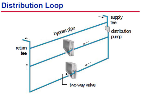
Seconadry Chilled Water Circuit သို့ distribution loop
 |
 |
The distribution pump သို့ Seconadry Chilled Water Pump သည္ the supply tee ေရကို the load
terminals (AHU/ FCU/CRAC Unit) မ်ားဆီသို့တြန္းပိုသည္။ ထို ေရသည္ AHU/ FCU/CRAC Unit မွ တဆင့္ the return tee ဆီသို့ၿပန္ေရာက္လာကာ Primary Chilled Water Circuit ဆီသုိ့ေရာက္သြားသည္။
terminals (AHU/ FCU/CRAC Unit) မ်ားဆီသို့တြန္းပိုသည္။ ထို ေရသည္ AHU/ FCU/CRAC Unit မွ တဆင့္ the return tee ဆီသို့ၿပန္ေရာက္လာကာ Primary Chilled Water Circuit ဆီသုိ့ေရာက္သြားသည္။
Primary Chilled Water Pump ႏွင့္ Seconadry Chilled
Water Pump သည္ same water ကို တြန္းပို့ေနၾကေသာ္လည္း there is no
duplication of pumping energy.အဘယ္ေၾကာင့္ဆုိေသာ Primary Chilled Water
Pump ၏ Head ကို Primary Chilled Water Circuit ၏ Friction Loss ကို
ေက်ာ္ရံု ဒီဇုိင္းလုပ္ထား (Select လုပ္ထား) ေသာေၾကာင့္ၿဖစ္သည္။ Seconadry
Chilled Water Pump ၏ Head ကို Seconadry Chilled Water Circuit ၏
Friction Loss ကို ေက်ာ္ရံု ဒီဇုိင္းလုပ္ထား (Select လုပ္ထား)
ေသာေၾကာင့္ၿဖစ္သည္၊
Seconadry Chilled Water Circuit ၏ ေရလည္ပတ္နွန္း
(chilled water flow rate) သည္ အေဆာက္အဦးတစ္ခုလံုး၏ Heat Load
ေပၚတြင္မူတည္သည္။ အေဆာက္အဦးတစ္ခုလံုး၏ Heat Load သည္ အခ်ိန္ႏွင့္
ရာသီဥတုကိုလုိက္၍ေၿပာင္းလဲေနသည္။ ထုိေၾကာင့္ Seconadry Chilled Water
Circuit ၏ ေရလည္ပတ္နွန္း (chilled water flow rate) သည္ အခ်ိန္ႏွင့္
ရာသီဥတုကိုလုိက္၍ေၿပာင္းလဲေနသည္။ ထိုေၾကာင့္ Seconadry Chilled Water Pump
ကို variable-speed drive (VSD) သို Variable Frequency Drive (VFD) ၿဖင့္
ေမာင္းႏွင္ရမည္။ ထုိ VSD သည္ part load သုိ့ လုိအပ္သည့္ အခ်ိန္ ၌လုိအပ္သည္
Speed (ie chilled water flow rate) ၿဖင့္ ေမာင္းႏွင္ေသာေၾကာင့္
စြမ္းအင္းေခြ်တာမူ(Energy Saving)လည္းၿဖစ္သည္။
Their use decreases the energy savings potential from
the variable-flow distribution pump. In fact, ASHRAE/IESNA Standard
90.1–1999 (Section 6.3.4.1) requires
the use of modulating two-way control valves, and thus variable water flow, in most systems. Primary-secondary systems comply with this requirement.
the use of modulating two-way control valves, and thus variable water flow, in most systems. Primary-secondary systems comply with this requirement.
 |
 |
| ဤကဲ့သို့ Common Header မွ Secondary Pump သည္ High Raise Building ကဲ့သို့ေသာ အေဆာက္အဦးမ်ားအတြက္သင့္ေလွ်ာ္သည္။ | ဤကဲ့သို့ Individal Secondary Pump မ်ားသည္ ေကာလိပ္ေက်ာင္းကဲ့သို့ေသာ မတူညီသည္ အေဆာက္အဦးမ်ား တစ္ခုၿခင္းစီ အတြက္ သင့္ေလွ်ာ္သည္။ |
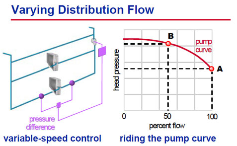
Seconadry Chilled Water Pump(The distribution pump
)ကို variable-speed drive ၿဖင့္ေမာင္းႏွင္သည္။ supply to load ပုိက္ႏွင့္
return to load ပိုက္ ၏ ဖိအားၿခားနားမူ (pressure difference between the
supply- and return-water piping) ကိုလုိက္ ၍variable-speed drive ကို
ေမာင္းႏွင္သည္။ ဖိအားၿခားနားမူ (pressure difference ) မ်ားလွ်င္
variable-speed drive သည္ ပန့္၏ လည္ပတ္ႏွဳန္း(Speed)ကိုေနွးေစသည္။
ဖိအားၿခားနားမူ ( differential pressure) နည္း လွ်င္ variable-speed drive
သည္ ပန့္၏ လည္ပတ္ႏွဳန္း(Speed)ကိုၿမန္ေစသည္။
AHU ႏွင့္ FCU တုိ့၏ the two-way valve modulates သည္
အေဆာက္အဦးတစ္ခုလံုး၏ Heat Load နည္းလာလွ်င္ တၿဖည္းၿဖည္းပိတ္သည္။ ထုိ
သုိ့ပိတ္မွဳေၾကာင့္ supply to load ပုိက္ႏွင့္ return to load
ပိုက္တုိ့အၾကားတြင္ system differential pressure
တၿဖည္းၿဖည္းၿမင့္တက္လာသည္။ ထုိဖိအားၿခားနားမူ ( differential pressure) ကို
Seconadry Chilled Water Pump(The distribution pump )၏ speed ကို
ေလွ်ာ့ခ်ရန္ signal အၿဖစ္အသံုးၿပဳသည္။
In response to a reduced cooling load, the two-way
valve modulates closed, restricting the flow of water through the coil.
This causes an
increase in system differential pressure, which can be measured and used to signal a reduction in the speed of the distribution pump.
increase in system differential pressure, which can be measured and used to signal a reduction in the speed of the distribution pump.
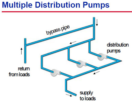
မည္သည့္ the distribution pumping arrangement မ်ိဳးၿဖစ္ပါေစ primary-secondary system ကို အသံုးၿပဳရန္သင့္ေလွ်ာ္သည္။
ေကာလိပ္ေက်ာင္းကဲ့သို့ေသာ မတူညီသည္ အေဆာက္အဦးမ်ား
တစ္ခုၿခင္းစီကို ပန့္တစ္လံုးၿခင္းစီၿဖင့္ multiple-pump configuration
မ်ိဳးၿဖင့္လည္းတပ္ဆင္နုိင္သည္။
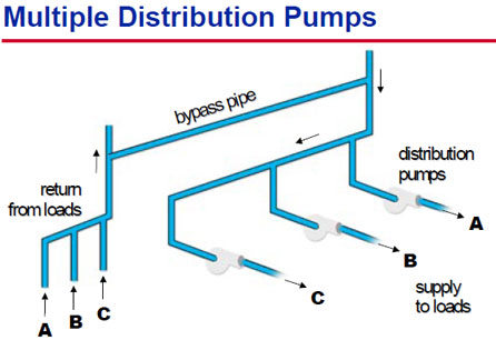
ဥပမာ the east Building (A), west Building (B), and
central Building (C) ဆီသို့ Separate distribution pumps (A),(B) ႏွင့္
(C) တုိ့ၿဖင့္ေမာင္းႏွင္ရန္တပ္ဆင္ထားသည္။
A primary advantage of this configuration is
flexibility. Expanding the system can be achieved by simply adding
another distribution pump to the existing plant and connecting it to the
piping that runs to the new building.

No comments:
Post a Comment
အခုလို လာေရာက္အားေပးၾကတာ အထူးပဲ ၀မ္းသာ ပီတိျဖစ္ရပါတယ္ဗ်ား ... ။ေက်းဇူးအထူးတင္ပါတယ္။
ေက်ာ္ထက္၀င္း နည္းပညာ (ဘားအံ)
www.kyawhtetwin.blogspot.com