Heat Exchanger- အပုိင္း-၁
Heat Exchanger မ်ားကို fluid တစ္မ်ိဳးမွ
အပူမ်ား(heat)ကို တစ္ၿခားေသာ fluid တစ္မ်ိဳးသို့ (ထုိ fluid တုိ့
တစ္ခုႏွင့္တစ္ခုထိေတြ ့ၿခင္းမရွိ)transfer လုပ္ရန္ အသံုးၿပဳသည္။
အပူခ်ိန္ၿမင့္မားသည့္ fluid ကို Hot fluid သုိ့ hot
medium ဟုေခၚၿပီး အပူခ်ိန္နိမ့္သည့္ fluid ကို cold fluid သုိ့ hot
medium ဟုေခၚသည္။ heat exchanger အတြင္းတြင္ အခ်ိဳ ့ေသာ fluid မ်ားသည္
အပူကို စုပ္ယူရင္း (Heat Gain) အရည္အၿဖစ္မွ အေငြ ့အၿဖစ္သုိ့
အသြင္ေၿပာင္းလဲၿခင္း (phase change) ၿဖစ္သည္။ ဥပမာ Refrigerant သည္
evaporator အတြင္းတြင္ Chilled Water မွ အပူကို စုပ္ယူ (Heat Gain)ကာ
liquid to a vapor အၿဖစ္သုိ့ေၿပာင္းသြားသည္။
အခ်ိဳ ့ေသာ fluid မ်ားသည္ အပူကို စြန္ထုပ္ရင္း (Heat
Loss) အေငြ ့အၿဖစ္မွ အရည္အၿဖစ္သုိ့ အသြင္ေၿပာင္းလဲၿခင္း (phase change)
ၿဖစ္သည္။ ဥပမာ Refrigerant သည္ condenser အတြင္းတြင္ Condenser Water
အတြင္းသုိ့ အပူကိုစြန့္ထုပ္ (Heat Loss )ကာ vapor to a liquid
အၿဖစ္သုိ့ေၿပာင္းသြားသည္။
ဤကဲ့သုိ့ fluid တစ္ခုမွ အၿခား fluid တစ္ခုသို့
အပူစြမ္းအင္ (Heat Energy) မ်ား transfer ၿဖစ္ၿခင္းသည္ fluid ႏွစ္ခု၏
အပူခ်ိန္ကြာဟ မွဳေၾကာင့္ၿဖစ္သည္။ heat exchangers မ်ားသည္ sensible heat
ႏွင့္ latent heat ႏွစ္မ်ိဳးလံုးကို transfer လုပ္နုိင္ၾကသည္။
Sensible heat မ်ား transfer ၿဖစ္ရန္
အသြင္ေၿပာင္းလဲၿခင္း (phase change) ၿဖစ္ေပၚရန္မလုိအပ္ေပ။ Latent heat
မ်ား transfer ၿဖစ္ရန္ heat exchanger အတြင္းတြင္
အသြင္ေၿပာင္းလဲၿခင္း (phase change) ၿဖစ္ေပၚရသည္။ Saturated Steam
အၿဖစ္မွ condensing steam ၿဖစ္ကာ Latent heat မ်ား transfer ၿဖစ္သြားသည္။
Heat Exchanger မ်ား၏ အေၿခခံသေဘာတရားမ်ား
(fundamentals), အမ်ိဳးအစားမ်ား(types), အစိတ္အပိုင္းမ်ား(components),
အသံုးၿပဳပံုမ်ား(applications), ေရႊးခ်ယ္ရန္ အခ်က္အလက္မ်ား (selection
criteria), ႏွင့္ တပ္ဆင္နည္း (installation) ကို ေဖာ္ၿပထားသည္။
FUNDAMENTALS
Hot fluid မွ cold fluid သို့ အပူစြမ္းအင္ (Heat Energy) မ်ား transfer
ၿဖစ္သည့္ႏွဳန္း (rate of heat transferred) ေအာက္ပါ
ေဖာ္ၿမဴလာအတုိင္းတြက္ခ်က္နုိင္ပါသည္။
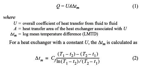
Q သည္ ကူးေၿပာင္းသြားသည့္ အပူပမာဏၿဖစ္သည္။
A သည္ Heat Transfer ၿဖစ္သည့္ ဧရိယာ အက်ယ္အဝန္းၿဖစ္သည္။
U သည္ Heat Exchanger တစ္ခုလံုး၏ overall coefficient of heat transfer ၿဖစ္သည္။
LMTD သည္ log mean temperature difference ၿဖစ္သည္။ logarithmic mean temperature
difference method ကုိ အေၿခခံ၍တြက္ၿခင္းၿဖစ္သည္။
LMTD တြင္ Cf သည္ correction factor ၿဖစ္သည္။ counterflow design
မၿဖစ္သည့္ Heat Exchanger မ်ား အတြက္ ၁ ထက္ အၿမဲတမ္းငယ္ေလ့ရွိသည္။ (less
than 1.0)
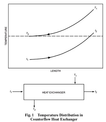 ပံု ၁ (အထက္ပါ) တြင္ အပူခ်ိန္ကြာၿခားခ်က္ (temperature cross) ေဖာ္ၿပထားသည္။ Hot fluid ကို Heating fluid ဟုေခၚသည္။
hot fluid ၏ အထြက္ အပူခ်ိန္သည္ cold fluid ၏ အထြက္ အပူခ်ိန္ထက္နည္းရမည္။ တနည္း (T2 < t2).
100% true counterflow arrangement ရွိသည့္ heat exchanger မ်ားသာ အပူခ်ိန္ကြာၿခားခ်က္ (temperature cross) ရရွိနုိင္သည္။
The overall coefficient U သည္ Heat Exchanger the surface area A ၏
physical arrangement ေပၚတြင္မူတည္သည္။ သတ္မွတ္ထားေသာ load တစ္ခုအတြက္
တူညီေသာ surface area ရွိသည့္ Heat Exchanger မ်ားအားလံုးသည္ တူညီေသာ
performance ကို ေပးနုိင္မည္မဟုတ္ေပ။ အဘယ္ေၾကာင့္ဆုိေသာ္ physical
arrangement မတူေသာေၾကာင့္ၿဖစ္သည္။ ထုိေၾကာင့္ heat exchanger ကို
ေရြးခ်ယ္သည့္အခါတြင္ မိမိလုိအပ္သည့္ application အတြက္ load conditions
ကို ေဖာ္ၿပေပးရမည္ၿဖစ္သည္။
Fluid ႏွစ္ခုလံုး၏ load ကို ေအာက္ပါ ေဖာ္ၿမဴလာၿဖင့္တြက္ယူနုိင္သည္။
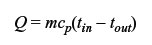
LMTD ၏ တန္ဘိုးသည္ heat exchanger selection အတြက္ အလြန္ အေရးၾကီးေသာ
အရာၿဖစ္သည္။ သတ္မွတ္ထားေသာ load အတြက္ LMTD ၏ တန္ဘိုးၿမင့္လွ်င္ ေသးငယ္ေသာ
surface area ရွိသည့္ heat exchange သာ လုိအပ္သည္။
တနည္း the approach temperature (the difference between T2 and t1) အလြန္နည္းလွ်င္ LMTD ၏ တန္ဘိုးလည္းနိမ့္သည္။ ထုိေၾကာင့္ Heat Transfer Surface ဧရိယာ (A) က်ယ္က်ယ္လုိအပ္သည္။
TYPES OF HEAT EXCHANGERS
Air con သုိ့ Refrigeration တြင္ အသံုးၿပဳေသာ heat exchanger မ်ားမွာ
က) Counterflow shell-and-tube heat exchanger အမ်ိဳးအစားမ်ား
ခ) Counterflow Plate heat exchanger အမ်ိဳးအစားမ်ားၿဖစ္ၾကသည္။
ႏွစ္မ်ိဳးစလံုးသည္ fluid မ်ားကို တစ္ခုႏွင္ ့တစ္ခုမထိေအာင္သီးၿခားခြဲထားၾကသည္။
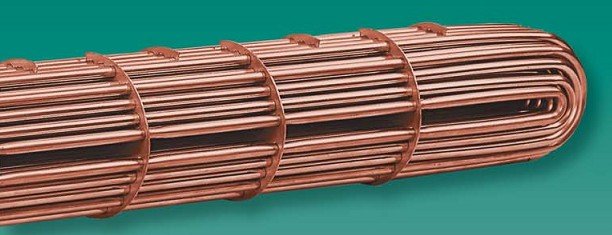
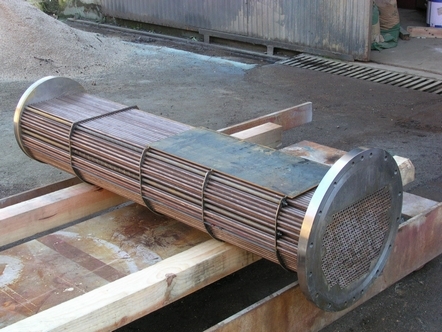
Shell-and-Tube Heat Exchangers
shell-and-tube heat exchanger အမ်ိဳးအစားသည္ tube bundle assembly ကို
tubular shell အတြင္းတြင္ welded လုပ္ထား၍ေသာ္လည္းေကာင္း၊ ဘုိ့ (bolts) နွင့္တြဲ၍ေသာ္လည္းေကာင္းတပ္ဆင္ထားသည္။
tube bundle မ်ားသည္ rolled သုိ့မဟုတ္ welded လုပ္ထားသည့္ (U-tube) မ်ားေသာ္လည္းေကာင္း၊ both
ends (straight-tube) မ်ားေသာ္လည္းေကာင္း၊ tubesheet(s) မ်ားေသာ္လည္းေကာင္းၿဖစ္ၾကသည္။
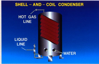
shell ဆုိသည္မွာ ပိုက္အၾကီးစားကုိ ၿဖတ္ထားၿပီး
longitudinal centerlines တြင္ inlet and outlet connections
ၿပဳလုပ္ထားသည္။ shell တြင္ ပံုစံမ်ား၊ အမ်ိဳးအစား မ်ားစြာ မကြာၿခားေပ။
သုိ့ေသာ္
Tube ပံုစံမ်ားတြင္
အသြင္ေၿပာင္းလဲၿခင္း (phase change) ၿဖစ္ေပၚရသည္။ Saturated Steam အၿဖစ္မွ condensing steam ၿဖစ္ကာ Latent heat မ်ား transfer ၿဖစ္သြားသည္။
Hot fluid မွ cold fluid သို့ အပူစြမ္းအင္ (Heat Energy) မ်ား transfer ၿဖစ္သည့္ႏွဳန္း (rate of heat transferred) ေအာက္ပါ ေဖာ္ၿမဴလာအတုိင္းတြက္ခ်က္နုိင္ပါသည္။
Q သည္ ကူးေၿပာင္းသြားသည့္ အပူပမာဏၿဖစ္သည္။
A သည္ Heat Transfer ၿဖစ္သည့္ ဧရိယာ အက်ယ္အဝန္းၿဖစ္သည္။
U သည္ Heat Exchanger တစ္ခုလံုး၏ overall coefficient of heat transfer ၿဖစ္သည္။
LMTD သည္ log mean temperature difference ၿဖစ္သည္။ logarithmic mean temperature
difference method ကုိ အေၿခခံ၍တြက္ၿခင္းၿဖစ္သည္။
LMTD တြင္ Cf သည္ correction factor ၿဖစ္သည္။ counterflow design မၿဖစ္သည့္ Heat Exchanger မ်ား အတြက္ ၁ ထက္ အၿမဲတမ္းငယ္ေလ့ရွိသည္။ (less than 1.0)
hot fluid ၏ အထြက္ အပူခ်ိန္သည္ cold fluid ၏ အထြက္ အပူခ်ိန္ထက္နည္းရမည္။ တနည္း (T2 < t2).
100% true counterflow arrangement ရွိသည့္ heat exchanger မ်ားသာ အပူခ်ိန္ကြာၿခားခ်က္ (temperature cross) ရရွိနုိင္သည္။
The overall coefficient U သည္ Heat Exchanger the surface area A ၏ physical arrangement ေပၚတြင္မူတည္သည္။ သတ္မွတ္ထားေသာ load တစ္ခုအတြက္ တူညီေသာ surface area ရွိသည့္ Heat Exchanger မ်ားအားလံုးသည္ တူညီေသာ performance ကို ေပးနုိင္မည္မဟုတ္ေပ။ အဘယ္ေၾကာင့္ဆုိေသာ္ physical arrangement မတူေသာေၾကာင့္ၿဖစ္သည္။ ထုိေၾကာင့္ heat exchanger ကို ေရြးခ်ယ္သည့္အခါတြင္ မိမိလုိအပ္သည့္ application အတြက္ load conditions ကို ေဖာ္ၿပေပးရမည္ၿဖစ္သည္။
LMTD ၏ တန္ဘိုးသည္ heat exchanger selection အတြက္ အလြန္ အေရးၾကီးေသာ အရာၿဖစ္သည္။ သတ္မွတ္ထားေသာ load အတြက္ LMTD ၏ တန္ဘိုးၿမင့္လွ်င္ ေသးငယ္ေသာ surface area ရွိသည့္ heat exchange သာ လုိအပ္သည္။
က) Counterflow shell-and-tube heat exchanger အမ်ိဳးအစားမ်ား
ခ) Counterflow Plate heat exchanger အမ်ိဳးအစားမ်ားၿဖစ္ၾကသည္။
ႏွစ္မ်ိဳးစလံုးသည္ fluid မ်ားကို တစ္ခုႏွင္ ့တစ္ခုမထိေအာင္သီးၿခားခြဲထားၾကသည္။
shell-and-tube heat exchanger အမ်ိဳးအစားသည္ tube bundle assembly ကို
tubular shell အတြင္းတြင္ welded လုပ္ထား၍ေသာ္လည္းေကာင္း၊ ဘုိ့ (bolts) နွင့္တြဲ၍ေသာ္လည္းေကာင္းတပ္ဆင္ထားသည္။
ends (straight-tube) မ်ားေသာ္လည္းေကာင္း၊ tubesheet(s) မ်ားေသာ္လည္းေကာင္းၿဖစ္ၾကသည္။
| ၁) U-Tube. | ||
 |
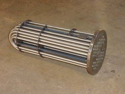 |
| ၂) Straight-Tube. | ||
 |
 |
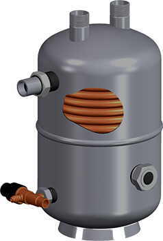
| ၃) Shell-and-Coil. | ||
 |
 |
Heat Exchanger- အပုိင္း-၂
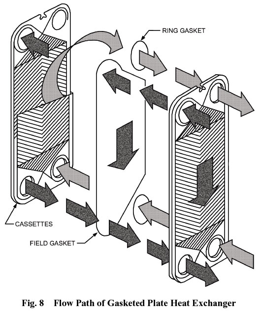
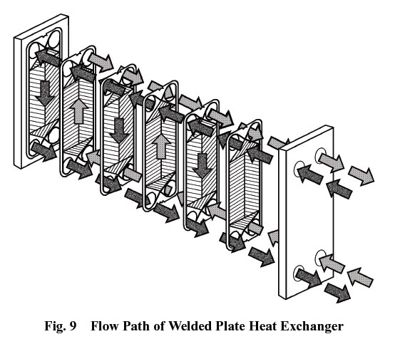
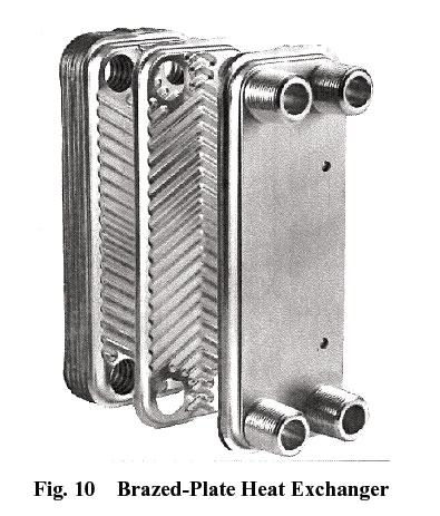
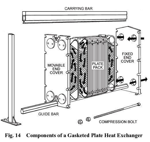 Plate Heat Exchangers
Plate heat exchangers ဆုိသည္မွာ hot fluid သီးသန့္ channel အတုိင္း
စီးရင္း၊ cold fluid သီးသန့္ channel အတုိင္း စီးရင္း၊ heat transfer
ၿဖစ္ေအာင္ metal plate အတြဲမ်ားကိုလုိက္ထပ္ထားၿခင္းၿဖစ္သည္။ အပူသည္ plate
နံရံမ်ား(plate walls)ကိုမွတဆင့္ၿဖတ္သန္းစီးဆင္းသြားသည္။
Exchanger တြင္ channel မ်ားကို တစ္ခုၿပီးတစ္ခု frame
တြဲ၍ ခ်ိတ္တြဲထားသည္။ plate မ်ား၏ ေထာင့္တြင္ အေပါက္ (opening or
port)မ်ားၿပဳလုပ္ထားသည္။ plate မ်ားအားလံုးကို အတူတကြတပ္ဆင္လုိက္လွ်င္ ထုိ
အေပါက္ (opening or port)မ်ားသည္ fluid မ်ားစီးဝင္ရန္ အတြက္ manifold
မ်ားအၿဖစ္သို့ေရာက္ရွိသြားသည္။ စီးဆင္းရာလမ္းေၾကာင္း(flow paths)ကို
ၿဖစ္ေစသည္။
Plate မ်ားစြာ ခ်ိတ္တြဲထားၿခင္းကို plate pack
ဟုေခၚသည္။ plate pack မ်ားကို ထိန္းထားေပးရန္ bar တစ္ခုလိုအပ္သည္။ ထုိသုိ့
ဒီဇုိင္းၿပဳလုပ္ထားၿခင္းေၾကာင့္ plate pack ကို ဖြင့္ ၿပီး plate
မ်ားတစ္ခုၿခင္းကို ေဆးေၾကာႏုိင္သည္။ Plate ထပ္ထည့္ၿခင္းၿဖင့္
ပိုမုိၿမင့္မားသည့္ Capacity လုိအပ္ပါ ရရွိနုိင္သည္။ ထုိအတူ မလုိအပ္သည့္
Plate မ်ားကို ၿဖဳတ္ထုပ္နုိင္သည္။
Plat ကို gasket မ်ားၿဖင့္ေသာ္လည္းေကာင္း- welding
ေဆာ္ၿခင္းၿဖင့္ေသာ္လည္းေကာင္း- brazing
လုပ္ၿခင္းၿဖင့္ေသာ္လည္းေကာင္းခ်ိတ္တြဲတပ္ဆင္နုိင္သည္။
Gasket မ်ားၿဖင့္ တပ္ဆင္ထားေသာ plate heat exchanger မ်ားသည္ အမ်ားဆံုး 2 MPa ဖိအားအထိသာ ခံနုိင္သည္။
အသံုးၿပဳသည့္ gasket material အမ်ိဳးအစား
(ရာဘာ-ပလပ္စတစ္ စသည္တို့)ကိုလုိက္၍ ခံနုိင္သည္ အပူခ်ိန္သည္ ကြာၿခားသည္။
Brazed plate မ်ားသည္ ဖိအား 3 MPa ႏွင့္ အပူခ်ိန္ (temperatures) 260°C
အထိခံနုိင္ၾကသည္။
Gasket plate heat exchanger မ်ားသည္
အသံုးမ်ားဆံုးၿဖစ္သည္။ nitrile butyl rubber (NBR) ၿဖင့္ၿပဳလုပ္ထားေသာ
gaskets မ်ားသည္ အပူခ်ိန္ 110°C အထိသာ ခံနုိင္ရည္ရွိသည္။
Ethylene-propylene terpolymer (EPDM) gaskets သည္ အပူခ်ိန္ 160°C အထိ
ခံနုိင္ရည္ရွိသည္။ gasket ကို plate ေပၚတြင္ ေကာ္ၿဖင့္ကပ္၍ေသာ္လည္းေကာင္း၊
ကလစ္မ်ားၿဖင့္ကပ္၍ေသာ္လည္းအသံုးၿပဳၾကသည္။
Gasket ပံုစံမ်ားကို counterflow လမ္းေၾကာင္းအတိုင္းစီးဆင္းသြားေအာင္ၿပဳလုပ္ထားၾကသည္။
Welded.
Plate ႏွစ္ခု၏အစြန္းကို ဂေဟေဆာ္ထားၿခင္းၿဖင့္တြဲထားလွ်င္ cassette ဟုေခၚသည္။ အက္စစ္မ်ား၊ သံေခ်းတတ္လြယ္ေသာ fluid မ်ားအတြက္ သင့္ေလွ်ာ္ေသာ
gasket material အမ်ိဳးအစား မရနုိင္လွ်င္ ဂေဟေဆာ္သည့္နည္းကို
အသံုးၿပဳသည္။ non-aggressive fluid မ်ားအတြက္ standard gasket မ်ားကို
အသံုးၿပဳၾကသည္။ refrigeration လုပ္ငန္းမ်ားအတြက္ ဂေဟေဆာ္သည့္ heat
exchanger မ်ားကို အသံုးၾကသည္လည္းရွိသည္။
Brazed.
gasket ႏွင့္ frame မ်ား သံုးမရသည့္ အခါ Brazed-plate
heat exchangers မ်ားကို ၿပဳလုပ္ၾကသည္။ copper or nickel အတံုးထဲတြင္
plates မ်ားကို ထည့္က brazing လုပ္ၿခင္းၿဖစ္သည္။
ၿပဳၿပင္ထိန္းသိမ္းရန္မလုိသည့္ closed-system applications မ်ားအတြက္
အလြန္ကုန္က်စရိတ္သက္သာသည့္ နည္းလမ္းေကာင္းၿဖစ္သည္။
heat exchanger နံရံမ်ား ေပါက္သြားသည့္ အခ်ိဳ ့ေသာ
fluid မ်ားသည္ အလြန္အႏၱရာယ္မ်ားသည္။ေပါက္ကြဲတတ္သည္။ ထုိေၾကာင့္ heat
exchanger နံရံမ်ားကိုနွစ္ထပ္ၿပဳလုပ္ထားၾကသည္။ Double-wall heat exchanger
ဟုေခၚသည္။ Double-wall heat exchangerကုိ shell-and-tube ႏွင့္ plate
heat exchangers ႏွစ္မ်ိဳးလံုးတြင္ရနုိင္သည္။
Double-wall heat exchanger ၏ overall thermal performance သည္ single-wall ေလာက္မေကာင္းေပ။ ေစ်းလည္းပိုမ်ားသည္။
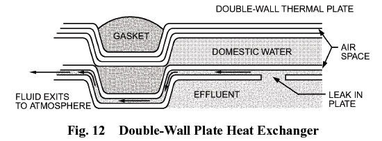 အထက္ပါ ပံု၁၂ တြင္double-wall plate heat exchanger တစ္ခု ၏welding ၿဖင့္ဆက္ထားေသာ Plate ႏွစ္ခု ႏွင့္ Gasket ကို ၿပထားသည္
COMPONENTS
HVAC applications အတြက္ ထုပ္လုပ္ သို့တည္ေဆာက္ထားေသာ Heat exchangers မ်ားတြင္ ASME Boiler and Pressure
Vessel Code ပါသည့္ ေလဘယ္မ်ားကို ေဖာ္ၿပထားရမည္ၿဖစ္ၿပီး အပူခ်ိန္ 190°C တြင္ ဖိအား 1000 kPa ကို အထိခံနုိင္ရမည္။
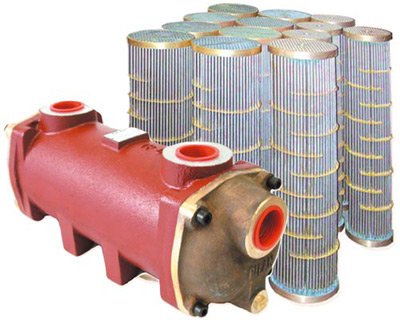
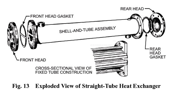 Shell-and-Tube Components
အထက္ပါပံု၁၃ တြင္ၿပထားသည့္ shell-and-tube exchanger တြင္ ေအာက္ပါ component မ်ားပါဝင္သည္။
Shell-and-Tube Components
အထက္ပါပံု၁၃ တြင္ၿပထားသည့္ shell-and-tube exchanger တြင္ ေအာက္ပါ component မ်ားပါဝင္သည္။
က) Shells
ခ) Baffles, tube supports, tie rods, and spacers
ဂ) Tubes
ဃ) Tubesheets
င) Heads တုိ့ပါဝင္သည္။
• Shells ကို steel pipe မ်ား၊ ေၾကး ႏွင့္ stainless
steel မ်ားၿဖင့္ၿပဳလုပ္ေလ့ရွိသည္။ The inlet and outlet nozzles မ်ားကို
တပ္ဆင္မွဳလြယ္ကူရန္ လူသံုးမ်ားသည့္ flange မ်ားၿဖင့္ ၿပဳလုပ္ထားသည္။
nozzles မ်ား၏ အဝ အက်ယ္ကို fluid velocity မ်ားေစရန္ႏွင့္ impingement on
the tubes ေပၚတြင္ impingement မၿဖစ္ေစရန္ ၿပဳလုပ္ထားသည္။
• Baffles, tube supports, tie rods, and spacers တုိ့
ကို ေၾကး ႏွင့္ stainless steel မ်ားၿဖင့္ၿပဳလုပ္ေလ့ရွိသည္။ baffle
အေရတြက္ႏွင့္ baffle တစ္ခုႏွင့္တစ္ခုအၾကားအကြာအေဝးသည္ velocity
နည္းၿခင္းမ်ားၿခင္းကိုၿဖစ္ေစသည္။ velocity မ်ားၿခင္းေၾကာင့္ shell-side
heat transfer coefficient က်ဆင္းၿပီး pressure drop ပိုမ်ားလာသည္။
• Tubes steel pipe မ်ား၊ ေၾကး၊ အထူးအရည္အေသြးေကာင္းေသာ brass မ်ား ႏွင့္ stainless steel မ်ားၿဖင့္ၿပဳလုပ္ေလ့ရွိသည္။
tube diameter, အထူ (gage) ႏွင့္ အမ်ိဳးအစား (material)
မ်ားသည္ heat transfer coefficient ႏွင့္ exchanger ၏ စြမ္းေဆာင္မွဳ
(performance) ကိုေၿပာင္းလဲေစသည္။ .
• Tubesheets မ်ားသည္ baffles ၿပဳလုပ္သည္ သတၱဳအမ်ိဳးအစားမ်ားနွင့္တူညီေလ့ရွိသည္။
Tubesheets မ်ားကို လုိအပ္သည့္ tube layout မ်ားအတုိင္း ရေအာင္အေပါက္မ်ားေဖာက္ေလ့ရွိသည္။ ထုိအေပါက္မ်ားပါေသာ tube layout ကို pitch ဟုေခၚေလ့ရွိသည္။
• Heads မ်ားကို အမ်ားအားၿဖင့္ cast iron သို့
fabricated steel ၿဖင့္ ၿပဳလုပ္ေလ့ရွိသည္။ ေသးငယ္ေသာ exchanger မ်ားအတြက္
Cast brass ႏွင့္ cast
stainless steel တုိ့ၿဖင့္လည္းၿပဳလုပ္ၾကသည္။ Head
မ်ားသည္လုိအပ္သည့္ေနရာ သို့ တပ္ဆင္မည့္ေနရာတို့ဝင္ အဆင္ေၿပေအာင္ အံဝင္ေအာင္
ၿပဳလုပ္ထားၾကသည္။
Plate Components
အထက္ပါပံုတြင္ Plate heat exchanger၏ gasketed plate ႏွင့္ frame တုိ့ကိုခြဲၿပထားသည္။
ေအာက္တြင္
Component မ်ား၏ လုပ္ေဆာင္ခ်က္မ်ားနွင့္ ၿပဳလုပ္သည့္ သတၱဳအမ်ိဳးအစားမ်ားကို ေဖာ္ၿပထားသည္။
• Fixed frame plates ကို carbon steelၿဖင့္ၿပဳလုပ္သည္။
Single-pass Plate heat exchanger တြင္ Hot fluid ႏွင့္
Cold fluid နွစ္မ်ိဳးလံုး၏ inlet and outlet တို့သည္ fixed frame plate
ဘက္တြင္သာရွိၾကသည္။ တနည္း fixed frame plate ဘက္တြင္ ပိုက္ Connection ၄
ခုလံုးရွိလွ်င္ Single-pass Plate heat exchanger ၿဖစ္သည္။ ANSI အမ်ိဳးအစား
flanges အတြက္ Connections မ်ားသည္ NPT သို့ stud port
ဒီဇုိင္းမ်ားၿဖစ္သည္။
NPT connections မ်ားသည္ carbon steel သုိ့ stainless steel
သတၱဳမ်ားၿဖစ္သည္။ Stud port connections မ်ားကို corrosion ၿဖစ္ၿခင္းမွ
ကာကြယ္ရန္အထဲတြင္ၿမဳတ္ထားေလ့ရွိသည္။
• Movable pressure plates ကို capacity တို့ရန္အတြက္
plates အသစ္မ်ားထပ္ထည့္ရန္၊ plates ထုပ္ၿဖစ္ရန္ ႏွင့္ plates အသစ္လဲလွယ္ရန္
ဒီဇုိင္းလုပ္ထားသည္။ Movable pressure plates သည္ carrying bar ၏
တစ္ေလွ်ာက္တြင္ ေရႊ ့နုိင္ ရန္ ္ ၿပဳလုပ္ ထားၿခင္းၿဖစ္သည္။carbon steel
ၿဖင့္ ၿပဳလုပ္ထားသည္။
• Plate packs မ်ားသည္ (channel) plates ႏွင့္ gaskets
တုိ့ၿဖင့္ၿပဳလုပ္ထားသည္။ Plates မ်ားသည္ stainless steel 316 အမ်ိဳးအစား၊
stainless steel 304 အမ်ိဳးအစား သုိ့ titanium မ်ားၿဖစ္သည္။herringbone
ပံုစံမ်ိဳး သို့ chevron ပံုစံမ်ိဳး ၿပဳလုပ္ေလ့ရွိသည္။ herringbone သို့
chevron pattern မ်ား ၏ ေထာင့္မ်ားသည္ the thermal performance ေကာင္းၿခင္း
ဆိုးၿခင္း ႏွင့္ pressure drop မ်ားၿခင္း။ နည္းၿခင္းတုိ့ကို ၿဖစ္ေစသည္။
Compression bolts မ်ားသည္ plate မ်ားကို Movable pressure plates ႏွင့္ Fixed frame plates တို့အတြင္းတြင္ ရွိေအာင္ ဖိထားၿခင္းၿဖစ္သည္။ ထုိေၾကာင့္ Fluid မ်ားမယုိစီးေတာ့ေပ။
• Carrying and guide bars မ်ားသည္ channel plates မ်ား အားထိန္းေပးထားၿခင္းၿဖစ္သည္။အေပၚတန္းကို carrying barဟုေခၚသည္။ ေအာက္တန္းကို guide bar ဟုေခၚသည္။
stainless steel, aluminum, သို့ carbon steel မ်ားၿဖင့္ၿပဳလုပ္ၿပီး zinc chromate ၿဖင့္ အေခ်ာသတ္သုတ္လိမ္းၾကသည္။
• Support columns သည္ plate heat exchangers မ်ားတြငcarrying and guide bars ထမ္းထားသည္။
• Splashguards မ်ားကို aluminum ၿဖင့္ၿပဳလုပ္သည္။
• Drip pans ကို stainless steel ၿဖင့္ၿပဳလုပ္သည္။
စတင္အသံုးၿပဳသည့္အခါ ။ shut down လုပ္သည့္အခါ ။ ယိုစီးၿခင္းၿဖစ္သည့္အခါ။
gasket မ်ားေပါက္ၿပဲသည့္အခါ။ ႏွင့္ condensation ၿဖစ္သည့္အခါမ်ားတြင္
ေရမ်ား ကို ေဘးသို့မေရာက္ေအာင္ စုေပးထားသည္။
APPLICATION
primary energy source တစ္ခုတည္းမွ မတူညီေသာ အပူခ်ိန္မ်ား။
မတူညီေသာအသံုးၿပဳမွဳမ်ားနွင့္ မတူညီေသာ စြမ္းအင္ပမာဏမ်ား အတြက္
လုိအပ္သည့္ေနရာတြင္ လုိအပ္သေလာက္ရွိရန္ Heat exchanger မ်ား
ကိုအသံုးၿပဳၾကသည္။
ASHRAE Handbook တြင္ ေဖာ္ၿပထားေသာ Heat exchangers အသံုးၿပဳပံုမ်ားမွာ
က) boiler မွ ထြက္လာသည့္ steam ကို central water systems အတြက္ hot water အၿဖစ္ condense လုပ္ရန္
ခ) ဟုိတယ္ႏွင့္ေဆးရုံမ်ားတြင္ လုိအပ္ေသာ Hot water system မ်ားတြင္အသံုးၿပဳရန္
ဂ) special temperature requirements လိုအပ္သည့္အခါ ႏွင့္ Hot fluid ႏွင့္ Cold Fluid တို့ သီးၿခား မေရာေႏွာ လုိအသည့္အခါ (isolation)
ဃ) energy-saving applications မ်ား အတြက္
င) refrigeration applications မ်ား အတြက္ (evaporators, condensers, and liquid coolers)
SELECTION CRITERIA
A heat exchanger ကို ကြန္ၿပဴတာ ပရုိဂရမ္မ်ား အသံုးၿပဳ၍ ေရြးခ်ယ္ၾကသည္။
ထုပ္လုပ္သူမ်ားႏွင့္ အၾကံေပးတုိင္ပင္ကာေရႊးခ်ယ္ေလ့ရွိသည္။
Thermal/Mechanical Design
Shell-and-tube heat exchangers မ်ားကို ဖိအားလိုအပ္ခ်က္ အရ ေရြးခ်ယ္ၾကရသည္။ ဒုတိယေနၿဖင့္ အပူ စီးကူးရန္ ေရြးခ်ယ္ၾကသည္။
Plate heat exchangers မ်ားကို ဖိအားလိုအပ္ခ်က္ မရွိသည့္ အခါမ်ိဳးတြင္ အေကာင္းဆံုးေသာ အပူ စီးကူးရန္ ၿဖစ္ရန္အတြက္ ေရြးခ်ယ္ၾကသည္။
Thermal Performance.
Heat exchanger ၏ thermal performance သည္ အရြယ္အစား(size) ႏွင့္
geometry of the heat transfer surface area တုိ့အေပၚတြင္မူတည္သည္။
Heat transfer surface ၏ materials အမ်ိဳးအစားသည္လည္း
performance ကို ေၿပာင္းလဲေစသည္။ ေၾကးနီသည္ stainless steel ထက္
အပူစီးကူးမွဳပိုေကာင္းသည္။(higher coefficient of heat transfer)
Fluid စီးႏွဳန္း Flow rates (velocity),
ေစးၿပစ္မွဳ(viscosity), ႏွင့္ အပူေလွ်ာက္ကူးမွဳ (thermal conductivity)
တုိ့သည္ overall heat transfer coefficient U ၏ တန္ဘိုးကို
ဆံုးၿဖစ္ေပးသည္။
shell-and-tube အမ်ိဳးအစား heat exchangers cold fluid
သည္ tube side အတြင္းတြင္ရွိရသည္။ အကယ္၍ cold fluid ကို shell side
ဘက္တြင္ စီးဆင္းပါက overall U ၏ တန္ဘုိးမွာက်ဆင္းသြားသည္။
Thermal Stress.
အပူခ်ိန္ကြာဟခ်က္ (large temperature differences) မ်ားသည့္ Heat exchanger မ်ားသည္ ၾကီးမားေသာ thermal
stresses ကို ခံရသည္။
fixed tubesheets မ်ားၿဖင့္ၿပဳလုပ္ထားသည့္ Heat
exchanger မ်ားသည္ အပူခ်ိန္ကြာဟခ်က္ (large temperature differences)
မ်ားသည့္ ၾကီးမားေသာ thermal
stresses ကို ခံနုိင္ရည္မရွိေပ။ ထုိအတူပင္ Gasketed plate units မ်ားသည္ ၾကီးမားေသာ thermal
stresses ကို ခံနုိင္ရည္မရွိေပ။
Pressure Drop. Fluid velocity and normal limitations on tube
length tend to result in relatively low pressure drops in shell-andtube
heat exchangers. Plate units tend to have larger pressure drops
unless the velocity is limited. Often a pressure drop limitation rather
than a thermal performance requirement determines the surface area
in a plate unit.
Fouling. Often, excess surface area is specified to allow for scale
accumulation on heat transfer surfaces without a significant reduction
of performance. This fouling factor or allowance is applied
when sizing the unit. Fouling allowance is better specified as a percentage
of excess area rather than as a resistance to heat transfer.
Shell-and-tube exchangers with properly sized tubes can handle
suspended solids better than plate units with narrow flow channels.
The high fluid velocity and turbulence in plate exchangers make
them less susceptible to fouling.
The addition of surface area (tube length) to a shell-and-tube
exchanger does not affect fluid velocity, and, therefore, has little
effect on thermal performance. This characteristic makes a fouling
allowance practical. This is not the case in plate units, for which the
number of parallel flow channels determines velocity. This means
that as plate pairs are added to meet a load (heat transfer surface
area) requirement, the number of channels increases and results in
decreased fluid velocity. This lower velocity reduces performance
and requires additional plate pairs, which further reduces performance.
Cost
On applications with temperature crosses and close approaches,
plate heat exchangers usually have the lowest initial cost. Wide
temperature approaches often favor shell-and-tube units. If the
application requires stainless steel, the plate unit may be more
economical.
Serviceability
Shell-and-tube heat exchangers have different degrees of serviceability.
The type of header used facilitates access to the inside of
the tubes. The heads illustrated in Figures 3, 6, and 7 can be easily
removed without special pipe arrangements. The tube bundles in all
of the shell-and-tube units illustrated, except the fixed-tubesheet
unit (Figure 6), can be replaced after the head is removed if they are
piped with proper clearance.
The diameter and configuration of the tubes are significant in
determining whether the inside of tubes of straight-tube units can be
mechanically cleaned. Figure 7 shows a type of head that allows
cleaning or inspection inside tubes after the channel cover is
removed.
Plate heat exchangers can be serviced by sliding the movable
pressure plate back along the carrying bars. Individual plates can be
removed for cleaning, regasketing, or replacement. Plate pairs can
be added for additional capacity. Complete replacement plate packs
can be installed.
Space Requirements
Cost-effective and efficient shell-and-tube heat exchangers
have small-diameter, long tubes. This configuration often challenges
the designer when allocating space required for service and
maintenance. For this reason, many shell-and-tube selections have
large diameters and short lengths. Although this selection performs
well, it often costs more than a smaller-diameter unit with
equal surface area. Be careful to provide adequate maintenance
clearance around heat exchangers. For shell-and-tube units, space
should be left clear so the tube bundle can be removed.
Plate heat exchangers tend to provide the most compact design in
terms of surface area for a given space.
Steam
Most HVAC applications using steam are designed with shell-and-
tube units. Plate heat exchangers are used in specialized industrial
and food processes with steam.
INSTALLATION
Control. Heat exchangers are usually controlled by a valve with
a temperature sensor. The sensor is placed in the flow stream of the
fluid to be heated or cooled. The valve regulates flow on the other
side of the heat exchanger to achieve the sensor set-point temperature.
Chapter 46 discusses control valves.
Piping. Heat exchangers should be piped such that air is easily
vented. Pipes must be able to be drained and accessible for service.
Pressure Relief. Safety pressure relief valves should be installed
on both sides between the heat exchanger and shutoff valves to
guard against damage from thermal expansion when the unit is not
in service, as well as to protect against overpressurization.
Flow Path. The intended flow path of each fluid on both sides of
a heat exchanger design should be followed. Failure to connect to
the correct inlet and outlet connections may reduce performance.
Condensate Removal. Heat exchangers that condense steam
require special installation. Proper removal of condensate is particularly
important. Inadequate drainage of condensate can result in
significant loss of capacity and even in mechanical failure.
Installing a vacuum breaker aids in draining condensate, particularly
when modulating steam control valves are used. Properly
sized and installed steam traps are critical. Chapter 10 discusses
steam traps and condensate removal.
Insulation. Heat exchangers are often insulated. Chapter 23 of
the 2005 ASHRAE Handbook—Fundamentals has further information
on insulation.
If you are intend to purchase a shell and tube heat
exchangers, you must consider 7 critical factors before deciding to
purchase one. Consider the following:
1) Heat exchanger tube diameter
The diameter of the tube can be manipulated by the provider. A key
point to consider is the nature of the particular liquids used in the
pipes. Smaller pipes warrant will clean faster, yet more pipes may be
less effective and less compact with respect to space.
2) Thickness of the tube
The thickness of the pipe refers to several factors. Corrosion, flow
resistance, axial force, pressure, and the availability of spare parts
in connection with a heat exchanger tube thickness.
3) Heat exchanger shell diameter and tube length
A heat exchanger costs is directly influenced by the shell diameter
and tube length. Customers who are concerned about the cost of heat
exchangers questions which the longest length of pipe to provide
without compromising its effectiveness. The possibility of long tubes
may be limited because of the limited space, specific job
specifications, capabilities and replacement.
4) Tube corrugation
The corrugation of tubes influences the performance of a shell and
tube heat exchanger. Corrugated cardboard, the tube increased
turbulence of fluids in turn deliver better results.
5) Tube Layout
“Tube layout ‘refers to how a heat exchanger tube is placed in the
skull. To date, four major layouts to consider: triangular, twisted
triangular, square and rotated square. Triangular tube facilitates a
better heat transfer, while the square tubing provides a longer period
of purity.
6) Tube pitch
“Tube pitch” refers to the distance between the centers of separate
but interconnected tubes. A general rule determines the pitch of a pipe
shall not be less than 1.25 times the outside diameter tubes.
7) Heat exchanger baffles
“Baffles” are used in shell and tube heat exchangers for liquid flow
in the direct beam. Baffles prevent tubes from sagging, and can also
prevent them from vibrating. Baffle spacing is important in relation to
pressure drop and heat transfer. Baffles closely shared a greater
pressure drop causes, but still too far apart may cause cooler spots
between them.
Plate heat exchangers ဆုိသည္မွာ hot fluid သီးသန့္ channel အတုိင္း စီးရင္း၊ cold fluid သီးသန့္ channel အတုိင္း စီးရင္း၊ heat transfer ၿဖစ္ေအာင္ metal plate အတြဲမ်ားကိုလုိက္ထပ္ထားၿခင္းၿဖစ္သည္။ အပူသည္ plate နံရံမ်ား(plate walls)ကိုမွတဆင့္ၿဖတ္သန္းစီးဆင္းသြားသည္။
Ethylene-propylene terpolymer (EPDM) gaskets သည္ အပူခ်ိန္ 160°C အထိ ခံနုိင္ရည္ရွိသည္။ gasket ကို plate ေပၚတြင္ ေကာ္ၿဖင့္ကပ္၍ေသာ္လည္းေကာင္း၊ ကလစ္မ်ားၿဖင့္ကပ္၍ေသာ္လည္းအသံုးၿပဳၾကသည္။
Plate ႏွစ္ခု၏အစြန္းကို ဂေဟေဆာ္ထားၿခင္းၿဖင့္တြဲထားလွ်င္ cassette ဟုေခၚသည္။ အက္စစ္မ်ား၊ သံေခ်းတတ္လြယ္ေသာ fluid မ်ားအတြက္ သင့္ေလွ်ာ္ေသာ gasket material အမ်ိဳးအစား မရနုိင္လွ်င္ ဂေဟေဆာ္သည့္နည္းကို အသံုးၿပဳသည္။ non-aggressive fluid မ်ားအတြက္ standard gasket မ်ားကို အသံုးၿပဳၾကသည္။ refrigeration လုပ္ငန္းမ်ားအတြက္ ဂေဟေဆာ္သည့္ heat exchanger မ်ားကို အသံုးၾကသည္လည္းရွိသည္။
Double-wall heat exchanger ၏ overall thermal performance သည္ single-wall ေလာက္မေကာင္းေပ။ ေစ်းလည္းပိုမ်ားသည္။
Vessel Code ပါသည့္ ေလဘယ္မ်ားကို ေဖာ္ၿပထားရမည္ၿဖစ္ၿပီး အပူခ်ိန္ 190°C တြင္ ဖိအား 1000 kPa ကို အထိခံနုိင္ရမည္။
က) Shells
• Shells ကို steel pipe မ်ား၊ ေၾကး ႏွင့္ stainless steel မ်ားၿဖင့္ၿပဳလုပ္ေလ့ရွိသည္။ The inlet and outlet nozzles မ်ားကို တပ္ဆင္မွဳလြယ္ကူရန္ လူသံုးမ်ားသည့္ flange မ်ားၿဖင့္ ၿပဳလုပ္ထားသည္။ nozzles မ်ား၏ အဝ အက်ယ္ကို fluid velocity မ်ားေစရန္ႏွင့္ impingement on the tubes ေပၚတြင္ impingement မၿဖစ္ေစရန္ ၿပဳလုပ္ထားသည္။
• Baffles, tube supports, tie rods, and spacers တုိ့ ကို ေၾကး ႏွင့္ stainless steel မ်ားၿဖင့္ၿပဳလုပ္ေလ့ရွိသည္။ baffle အေရတြက္ႏွင့္ baffle တစ္ခုႏွင့္တစ္ခုအၾကားအကြာအေဝးသည္ velocity နည္းၿခင္းမ်ားၿခင္းကိုၿဖစ္ေစသည္။ velocity မ်ားၿခင္းေၾကာင့္ shell-side heat transfer coefficient က်ဆင္းၿပီး pressure drop ပိုမ်ားလာသည္။
• Tubes steel pipe မ်ား၊ ေၾကး၊ အထူးအရည္အေသြးေကာင္းေသာ brass မ်ား ႏွင့္ stainless steel မ်ားၿဖင့္ၿပဳလုပ္ေလ့ရွိသည္။
• Tubesheets မ်ားသည္ baffles ၿပဳလုပ္သည္ သတၱဳအမ်ိဳးအစားမ်ားနွင့္တူညီေလ့ရွိသည္။
Tubesheets မ်ားကို လုိအပ္သည့္ tube layout မ်ားအတုိင္း ရေအာင္အေပါက္မ်ားေဖာက္ေလ့ရွိသည္။ ထုိအေပါက္မ်ားပါေသာ tube layout ကို pitch ဟုေခၚေလ့ရွိသည္။
• Heads မ်ားကို အမ်ားအားၿဖင့္ cast iron သို့ fabricated steel ၿဖင့္ ၿပဳလုပ္ေလ့ရွိသည္။ ေသးငယ္ေသာ exchanger မ်ားအတြက္ Cast brass ႏွင့္ cast
stainless steel တုိ့ၿဖင့္လည္းၿပဳလုပ္ၾကသည္။ Head မ်ားသည္လုိအပ္သည့္ေနရာ သို့ တပ္ဆင္မည့္ေနရာတို့ဝင္ အဆင္ေၿပေအာင္ အံဝင္ေအာင္ ၿပဳလုပ္ထားၾကသည္။
Plate Components
ေအာက္တြင္ Component မ်ား၏ လုပ္ေဆာင္ခ်က္မ်ားနွင့္ ၿပဳလုပ္သည့္ သတၱဳအမ်ိဳးအစားမ်ားကို ေဖာ္ၿပထားသည္။
• Fixed frame plates ကို carbon steelၿဖင့္ၿပဳလုပ္သည္။
NPT connections မ်ားသည္ carbon steel သုိ့ stainless steel သတၱဳမ်ားၿဖစ္သည္။ Stud port connections မ်ားကို corrosion ၿဖစ္ၿခင္းမွ ကာကြယ္ရန္အထဲတြင္ၿမဳတ္ထားေလ့ရွိသည္။
• Movable pressure plates ကို capacity တို့ရန္အတြက္ plates အသစ္မ်ားထပ္ထည့္ရန္၊ plates ထုပ္ၿဖစ္ရန္ ႏွင့္ plates အသစ္လဲလွယ္ရန္ ဒီဇုိင္းလုပ္ထားသည္။ Movable pressure plates သည္ carrying bar ၏ တစ္ေလွ်ာက္တြင္ ေရႊ ့နုိင္ ရန္ ္ ၿပဳလုပ္ ထားၿခင္းၿဖစ္သည္။carbon steel ၿဖင့္ ၿပဳလုပ္ထားသည္။
• Plate packs မ်ားသည္ (channel) plates ႏွင့္ gaskets တုိ့ၿဖင့္ၿပဳလုပ္ထားသည္။ Plates မ်ားသည္ stainless steel 316 အမ်ိဳးအစား၊ stainless steel 304 အမ်ိဳးအစား သုိ့ titanium မ်ားၿဖစ္သည္။herringbone ပံုစံမ်ိဳး သို့ chevron ပံုစံမ်ိဳး ၿပဳလုပ္ေလ့ရွိသည္။ herringbone သို့ chevron pattern မ်ား ၏ ေထာင့္မ်ားသည္ the thermal performance ေကာင္းၿခင္း ဆိုးၿခင္း ႏွင့္ pressure drop မ်ားၿခင္း။ နည္းၿခင္းတုိ့ကို ၿဖစ္ေစသည္။
Compression bolts မ်ားသည္ plate မ်ားကို Movable pressure plates ႏွင့္ Fixed frame plates တို့အတြင္းတြင္ ရွိေအာင္ ဖိထားၿခင္းၿဖစ္သည္။ ထုိေၾကာင့္ Fluid မ်ားမယုိစီးေတာ့ေပ။
stainless steel, aluminum, သို့ carbon steel မ်ားၿဖင့္ၿပဳလုပ္ၿပီး zinc chromate ၿဖင့္ အေခ်ာသတ္သုတ္လိမ္းၾကသည္။
• Support columns သည္ plate heat exchangers မ်ားတြငcarrying and guide bars ထမ္းထားသည္။
• Splashguards မ်ားကို aluminum ၿဖင့္ၿပဳလုပ္သည္။
• Drip pans ကို stainless steel ၿဖင့္ၿပဳလုပ္သည္။ စတင္အသံုးၿပဳသည့္အခါ ။ shut down လုပ္သည့္အခါ ။ ယိုစီးၿခင္းၿဖစ္သည့္အခါ။ gasket မ်ားေပါက္ၿပဲသည့္အခါ။ ႏွင့္ condensation ၿဖစ္သည့္အခါမ်ားတြင္ ေရမ်ား ကို ေဘးသို့မေရာက္ေအာင္ စုေပးထားသည္။
APPLICATION
primary energy source တစ္ခုတည္းမွ မတူညီေသာ အပူခ်ိန္မ်ား။
မတူညီေသာအသံုးၿပဳမွဳမ်ားနွင့္ မတူညီေသာ စြမ္းအင္ပမာဏမ်ား အတြက္
လုိအပ္သည့္ေနရာတြင္ လုိအပ္သေလာက္ရွိရန္ Heat exchanger မ်ား
ကိုအသံုးၿပဳၾကသည္။
ASHRAE Handbook တြင္ ေဖာ္ၿပထားေသာ Heat exchangers အသံုးၿပဳပံုမ်ားမွာ
က) boiler မွ ထြက္လာသည့္ steam ကို central water systems အတြက္ hot water အၿဖစ္ condense လုပ္ရန္
ခ) ဟုိတယ္ႏွင့္ေဆးရုံမ်ားတြင္ လုိအပ္ေသာ Hot water system မ်ားတြင္အသံုးၿပဳရန္
ဂ) special temperature requirements လိုအပ္သည့္အခါ ႏွင့္ Hot fluid ႏွင့္ Cold Fluid တို့ သီးၿခား မေရာေႏွာ လုိအသည့္အခါ (isolation)
ဃ) energy-saving applications မ်ား အတြက္
င) refrigeration applications မ်ား အတြက္ (evaporators, condensers, and liquid coolers)
SELECTION CRITERIA
A heat exchanger ကို ကြန္ၿပဴတာ ပရုိဂရမ္မ်ား အသံုးၿပဳ၍ ေရြးခ်ယ္ၾကသည္။
ထုပ္လုပ္သူမ်ားႏွင့္ အၾကံေပးတုိင္ပင္ကာေရႊးခ်ယ္ေလ့ရွိသည္။
Thermal/Mechanical Design
Shell-and-tube heat exchangers မ်ားကို ဖိအားလိုအပ္ခ်က္ အရ ေရြးခ်ယ္ၾကရသည္။ ဒုတိယေနၿဖင့္ အပူ စီးကူးရန္ ေရြးခ်ယ္ၾကသည္။
Plate heat exchangers မ်ားကို ဖိအားလိုအပ္ခ်က္ မရွိသည့္ အခါမ်ိဳးတြင္ အေကာင္းဆံုးေသာ အပူ စီးကူးရန္ ၿဖစ္ရန္အတြက္ ေရြးခ်ယ္ၾကသည္။
Thermal Performance.
Heat exchanger ၏ thermal performance သည္ အရြယ္အစား(size) ႏွင့္
geometry of the heat transfer surface area တုိ့အေပၚတြင္မူတည္သည္။
Heat transfer surface ၏ materials အမ်ိဳးအစားသည္လည္း
performance ကို ေၿပာင္းလဲေစသည္။ ေၾကးနီသည္ stainless steel ထက္
အပူစီးကူးမွဳပိုေကာင္းသည္။(higher coefficient of heat transfer)
Fluid စီးႏွဳန္း Flow rates (velocity),
ေစးၿပစ္မွဳ(viscosity), ႏွင့္ အပူေလွ်ာက္ကူးမွဳ (thermal conductivity)
တုိ့သည္ overall heat transfer coefficient U ၏ တန္ဘိုးကို
ဆံုးၿဖစ္ေပးသည္။
shell-and-tube အမ်ိဳးအစား heat exchangers cold fluid
သည္ tube side အတြင္းတြင္ရွိရသည္။ အကယ္၍ cold fluid ကို shell side
ဘက္တြင္ စီးဆင္းပါက overall U ၏ တန္ဘုိးမွာက်ဆင္းသြားသည္။
Thermal Stress.
အပူခ်ိန္ကြာဟခ်က္ (large temperature differences) မ်ားသည့္ Heat exchanger မ်ားသည္ ၾကီးမားေသာ thermal
stresses ကို ခံရသည္။
fixed tubesheets မ်ားၿဖင့္ၿပဳလုပ္ထားသည့္ Heat
exchanger မ်ားသည္ အပူခ်ိန္ကြာဟခ်က္ (large temperature differences)
မ်ားသည့္ ၾကီးမားေသာ thermal
stresses ကို ခံနုိင္ရည္မရွိေပ။ ထုိအတူပင္ Gasketed plate units မ်ားသည္ ၾကီးမားေသာ thermal
stresses ကို ခံနုိင္ရည္မရွိေပ။
Pressure Drop. Fluid velocity and normal limitations on tube
length tend to result in relatively low pressure drops in shell-andtube
heat exchangers. Plate units tend to have larger pressure drops
unless the velocity is limited. Often a pressure drop limitation rather
than a thermal performance requirement determines the surface area
in a plate unit.
Fouling. Often, excess surface area is specified to allow for scale
accumulation on heat transfer surfaces without a significant reduction
of performance. This fouling factor or allowance is applied
when sizing the unit. Fouling allowance is better specified as a percentage
of excess area rather than as a resistance to heat transfer.
Shell-and-tube exchangers with properly sized tubes can handle
suspended solids better than plate units with narrow flow channels.
The high fluid velocity and turbulence in plate exchangers make
them less susceptible to fouling.
The addition of surface area (tube length) to a shell-and-tube
exchanger does not affect fluid velocity, and, therefore, has little
effect on thermal performance. This characteristic makes a fouling
allowance practical. This is not the case in plate units, for which the
number of parallel flow channels determines velocity. This means
that as plate pairs are added to meet a load (heat transfer surface
area) requirement, the number of channels increases and results in
decreased fluid velocity. This lower velocity reduces performance
and requires additional plate pairs, which further reduces performance.
Cost
On applications with temperature crosses and close approaches,
plate heat exchangers usually have the lowest initial cost. Wide
temperature approaches often favor shell-and-tube units. If the
application requires stainless steel, the plate unit may be more
economical.
Serviceability
Shell-and-tube heat exchangers have different degrees of serviceability.
The type of header used facilitates access to the inside of
the tubes. The heads illustrated in Figures 3, 6, and 7 can be easily
removed without special pipe arrangements. The tube bundles in all
of the shell-and-tube units illustrated, except the fixed-tubesheet
unit (Figure 6), can be replaced after the head is removed if they are
piped with proper clearance.
The diameter and configuration of the tubes are significant in
determining whether the inside of tubes of straight-tube units can be
mechanically cleaned. Figure 7 shows a type of head that allows
cleaning or inspection inside tubes after the channel cover is
removed.
Plate heat exchangers can be serviced by sliding the movable
pressure plate back along the carrying bars. Individual plates can be
removed for cleaning, regasketing, or replacement. Plate pairs can
be added for additional capacity. Complete replacement plate packs
can be installed.
Space Requirements
Cost-effective and efficient shell-and-tube heat exchangers
have small-diameter, long tubes. This configuration often challenges
the designer when allocating space required for service and
maintenance. For this reason, many shell-and-tube selections have
large diameters and short lengths. Although this selection performs
well, it often costs more than a smaller-diameter unit with
equal surface area. Be careful to provide adequate maintenance
clearance around heat exchangers. For shell-and-tube units, space
should be left clear so the tube bundle can be removed.
Plate heat exchangers tend to provide the most compact design in
terms of surface area for a given space.
Steam
Most HVAC applications using steam are designed with shell-and-
tube units. Plate heat exchangers are used in specialized industrial
and food processes with steam.
INSTALLATION
Control. Heat exchangers are usually controlled by a valve with
a temperature sensor. The sensor is placed in the flow stream of the
fluid to be heated or cooled. The valve regulates flow on the other
side of the heat exchanger to achieve the sensor set-point temperature.
Chapter 46 discusses control valves.
Piping. Heat exchangers should be piped such that air is easily
vented. Pipes must be able to be drained and accessible for service.
Pressure Relief. Safety pressure relief valves should be installed
on both sides between the heat exchanger and shutoff valves to
guard against damage from thermal expansion when the unit is not
in service, as well as to protect against overpressurization.
Flow Path. The intended flow path of each fluid on both sides of
a heat exchanger design should be followed. Failure to connect to
the correct inlet and outlet connections may reduce performance.
Condensate Removal. Heat exchangers that condense steam
require special installation. Proper removal of condensate is particularly
important. Inadequate drainage of condensate can result in
significant loss of capacity and even in mechanical failure.
Installing a vacuum breaker aids in draining condensate, particularly
when modulating steam control valves are used. Properly
sized and installed steam traps are critical. Chapter 10 discusses
steam traps and condensate removal.
Insulation. Heat exchangers are often insulated. Chapter 23 of
the 2005 ASHRAE Handbook—Fundamentals has further information
on insulation.
If you are intend to purchase a shell and tube heat
exchangers, you must consider 7 critical factors before deciding to
purchase one. Consider the following:
1) Heat exchanger tube diameter
The diameter of the tube can be manipulated by the provider. A key
point to consider is the nature of the particular liquids used in the
pipes. Smaller pipes warrant will clean faster, yet more pipes may be
less effective and less compact with respect to space.
2) Thickness of the tube
The thickness of the pipe refers to several factors. Corrosion, flow
resistance, axial force, pressure, and the availability of spare parts
in connection with a heat exchanger tube thickness.
3) Heat exchanger shell diameter and tube length
A heat exchanger costs is directly influenced by the shell diameter
and tube length. Customers who are concerned about the cost of heat
exchangers questions which the longest length of pipe to provide
without compromising its effectiveness. The possibility of long tubes
may be limited because of the limited space, specific job
specifications, capabilities and replacement.
4) Tube corrugation
The corrugation of tubes influences the performance of a shell and
tube heat exchanger. Corrugated cardboard, the tube increased
turbulence of fluids in turn deliver better results.
5) Tube Layout
“Tube layout ‘refers to how a heat exchanger tube is placed in the
skull. To date, four major layouts to consider: triangular, twisted
triangular, square and rotated square. Triangular tube facilitates a
better heat transfer, while the square tubing provides a longer period
of purity.
6) Tube pitch
“Tube pitch” refers to the distance between the centers of separate
but interconnected tubes. A general rule determines the pitch of a pipe
shall not be less than 1.25 times the outside diameter tubes.
7) Heat exchanger baffles
“Baffles” are used in shell and tube heat exchangers for liquid flow
in the direct beam. Baffles prevent tubes from sagging, and can also
prevent them from vibrating. Baffle spacing is important in relation to
pressure drop and heat transfer. Baffles closely shared a greater
pressure drop causes, but still too far apart may cause cooler spots
between them.
primary energy source တစ္ခုတည္းမွ မတူညီေသာ အပူခ်ိန္မ်ား။ မတူညီေသာအသံုးၿပဳမွဳမ်ားနွင့္ မတူညီေသာ စြမ္းအင္ပမာဏမ်ား အတြက္ လုိအပ္သည့္ေနရာတြင္ လုိအပ္သေလာက္ရွိရန္ Heat exchanger မ်ား ကိုအသံုးၿပဳၾကသည္။
ASHRAE Handbook တြင္ ေဖာ္ၿပထားေသာ Heat exchangers အသံုးၿပဳပံုမ်ားမွာ
ခ) ဟုိတယ္ႏွင့္ေဆးရုံမ်ားတြင္ လုိအပ္ေသာ Hot water system မ်ားတြင္အသံုးၿပဳရန္
ဃ) energy-saving applications မ်ား အတြက္
င) refrigeration applications မ်ား အတြက္ (evaporators, condensers, and liquid coolers)
SELECTION CRITERIA
A heat exchanger ကို ကြန္ၿပဴတာ ပရုိဂရမ္မ်ား အသံုးၿပဳ၍ ေရြးခ်ယ္ၾကသည္။ ထုပ္လုပ္သူမ်ားႏွင့္ အၾကံေပးတုိင္ပင္ကာေရႊးခ်ယ္ေလ့ရွိသည္။
Shell-and-tube heat exchangers မ်ားကို ဖိအားလိုအပ္ခ်က္ အရ ေရြးခ်ယ္ၾကရသည္။ ဒုတိယေနၿဖင့္ အပူ စီးကူးရန္ ေရြးခ်ယ္ၾကသည္။
Heat exchanger ၏ thermal performance သည္ အရြယ္အစား(size) ႏွင့္ geometry of the heat transfer surface area တုိ့အေပၚတြင္မူတည္သည္။
stresses ကို ခံရသည္။
stresses ကို ခံနုိင္ရည္မရွိေပ။ ထုိအတူပင္ Gasketed plate units မ်ားသည္ ၾကီးမားေသာ thermal
stresses ကို ခံနုိင္ရည္မရွိေပ။
length tend to result in relatively low pressure drops in shell-andtube
heat exchangers. Plate units tend to have larger pressure drops
unless the velocity is limited. Often a pressure drop limitation rather
than a thermal performance requirement determines the surface area
in a plate unit.
Fouling. Often, excess surface area is specified to allow for scale
accumulation on heat transfer surfaces without a significant reduction
of performance. This fouling factor or allowance is applied
when sizing the unit. Fouling allowance is better specified as a percentage
of excess area rather than as a resistance to heat transfer.
Shell-and-tube exchangers with properly sized tubes can handle
suspended solids better than plate units with narrow flow channels.
The high fluid velocity and turbulence in plate exchangers make
them less susceptible to fouling.
The addition of surface area (tube length) to a shell-and-tube
exchanger does not affect fluid velocity, and, therefore, has little
effect on thermal performance. This characteristic makes a fouling
allowance practical. This is not the case in plate units, for which the
number of parallel flow channels determines velocity. This means
that as plate pairs are added to meet a load (heat transfer surface
area) requirement, the number of channels increases and results in
decreased fluid velocity. This lower velocity reduces performance
and requires additional plate pairs, which further reduces performance.
On applications with temperature crosses and close approaches,
plate heat exchangers usually have the lowest initial cost. Wide
temperature approaches often favor shell-and-tube units. If the
application requires stainless steel, the plate unit may be more
economical.
Shell-and-tube heat exchangers have different degrees of serviceability.
The type of header used facilitates access to the inside of
the tubes. The heads illustrated in Figures 3, 6, and 7 can be easily
removed without special pipe arrangements. The tube bundles in all
of the shell-and-tube units illustrated, except the fixed-tubesheet
unit (Figure 6), can be replaced after the head is removed if they are
piped with proper clearance.
The diameter and configuration of the tubes are significant in
determining whether the inside of tubes of straight-tube units can be
mechanically cleaned. Figure 7 shows a type of head that allows
cleaning or inspection inside tubes after the channel cover is
removed.
Plate heat exchangers can be serviced by sliding the movable
pressure plate back along the carrying bars. Individual plates can be
removed for cleaning, regasketing, or replacement. Plate pairs can
be added for additional capacity. Complete replacement plate packs
can be installed.
Cost-effective and efficient shell-and-tube heat exchangers
have small-diameter, long tubes. This configuration often challenges
the designer when allocating space required for service and
maintenance. For this reason, many shell-and-tube selections have
large diameters and short lengths. Although this selection performs
well, it often costs more than a smaller-diameter unit with
equal surface area. Be careful to provide adequate maintenance
clearance around heat exchangers. For shell-and-tube units, space
should be left clear so the tube bundle can be removed.
Plate heat exchangers tend to provide the most compact design in
terms of surface area for a given space.
Most HVAC applications using steam are designed with shell-and-
tube units. Plate heat exchangers are used in specialized industrial
and food processes with steam.
Control. Heat exchangers are usually controlled by a valve with
a temperature sensor. The sensor is placed in the flow stream of the
fluid to be heated or cooled. The valve regulates flow on the other
side of the heat exchanger to achieve the sensor set-point temperature.
Chapter 46 discusses control valves.
Piping. Heat exchangers should be piped such that air is easily
vented. Pipes must be able to be drained and accessible for service.
Pressure Relief. Safety pressure relief valves should be installed
on both sides between the heat exchanger and shutoff valves to
guard against damage from thermal expansion when the unit is not
in service, as well as to protect against overpressurization.
Flow Path. The intended flow path of each fluid on both sides of
a heat exchanger design should be followed. Failure to connect to
the correct inlet and outlet connections may reduce performance.
Condensate Removal. Heat exchangers that condense steam
require special installation. Proper removal of condensate is particularly
important. Inadequate drainage of condensate can result in
significant loss of capacity and even in mechanical failure.
Installing a vacuum breaker aids in draining condensate, particularly
when modulating steam control valves are used. Properly
sized and installed steam traps are critical. Chapter 10 discusses
steam traps and condensate removal.
Insulation. Heat exchangers are often insulated. Chapter 23 of
the 2005 ASHRAE Handbook—Fundamentals has further information
on insulation.
1) Heat exchanger tube diameter
The diameter of the tube can be manipulated by the provider. A key point to consider is the nature of the particular liquids used in the pipes. Smaller pipes warrant will clean faster, yet more pipes may be less effective and less compact with respect to space.
2) Thickness of the tube
The thickness of the pipe refers to several factors. Corrosion, flow resistance, axial force, pressure, and the availability of spare parts in connection with a heat exchanger tube thickness.
3) Heat exchanger shell diameter and tube length
A heat exchanger costs is directly influenced by the shell diameter and tube length. Customers who are concerned about the cost of heat exchangers questions which the longest length of pipe to provide without compromising its effectiveness. The possibility of long tubes may be limited because of the limited space, specific job specifications, capabilities and replacement.
4) Tube corrugation
The corrugation of tubes influences the performance of a shell and tube heat exchanger. Corrugated cardboard, the tube increased turbulence of fluids in turn deliver better results.
5) Tube Layout
“Tube layout ‘refers to how a heat exchanger tube is placed in the skull. To date, four major layouts to consider: triangular, twisted triangular, square and rotated square. Triangular tube facilitates a better heat transfer, while the square tubing provides a longer period of purity.
6) Tube pitch
“Tube pitch” refers to the distance between the centers of separate but interconnected tubes. A general rule determines the pitch of a pipe shall not be less than 1.25 times the outside diameter tubes.
7) Heat exchanger baffles
“Baffles” are used in shell and tube heat exchangers for liquid flow in the direct beam. Baffles prevent tubes from sagging, and can also prevent them from vibrating. Baffle spacing is important in relation to pressure drop and heat transfer. Baffles closely shared a greater pressure drop causes, but still too far apart may cause cooler spots between them.

No comments:
Post a Comment
အခုလို လာေရာက္အားေပးၾကတာ အထူးပဲ ၀မ္းသာ ပီတိျဖစ္ရပါတယ္ဗ်ား ... ။ေက်းဇူးအထူးတင္ပါတယ္။
ေက်ာ္ထက္၀င္း နည္းပညာ (ဘားအံ)
www.kyawhtetwin.blogspot.com